

I have a drawer full of cheap kits and I’m on a mission to empty it! This time, I’m looking at a “generic” CD4060 SMD “musical” LED fancy lantern kit which was purchased for AU$2.89 including postage. What’s so fancy about a few LEDs, I wonder?
The big difference is that this kit advertises its SMD nature – I suppose this is a challenge that might appeal to some … maybe good practice or experimentation for those new to SMD (like myself).
The Kit

We’re back to zip-lock-bag goodness …

Inside, we get the PCB, three-sets of four LEDs, a few diodes and transistors, a capacitor, a switch, potentiometer, speaker, IC, chip-on-board and SMD resistors.

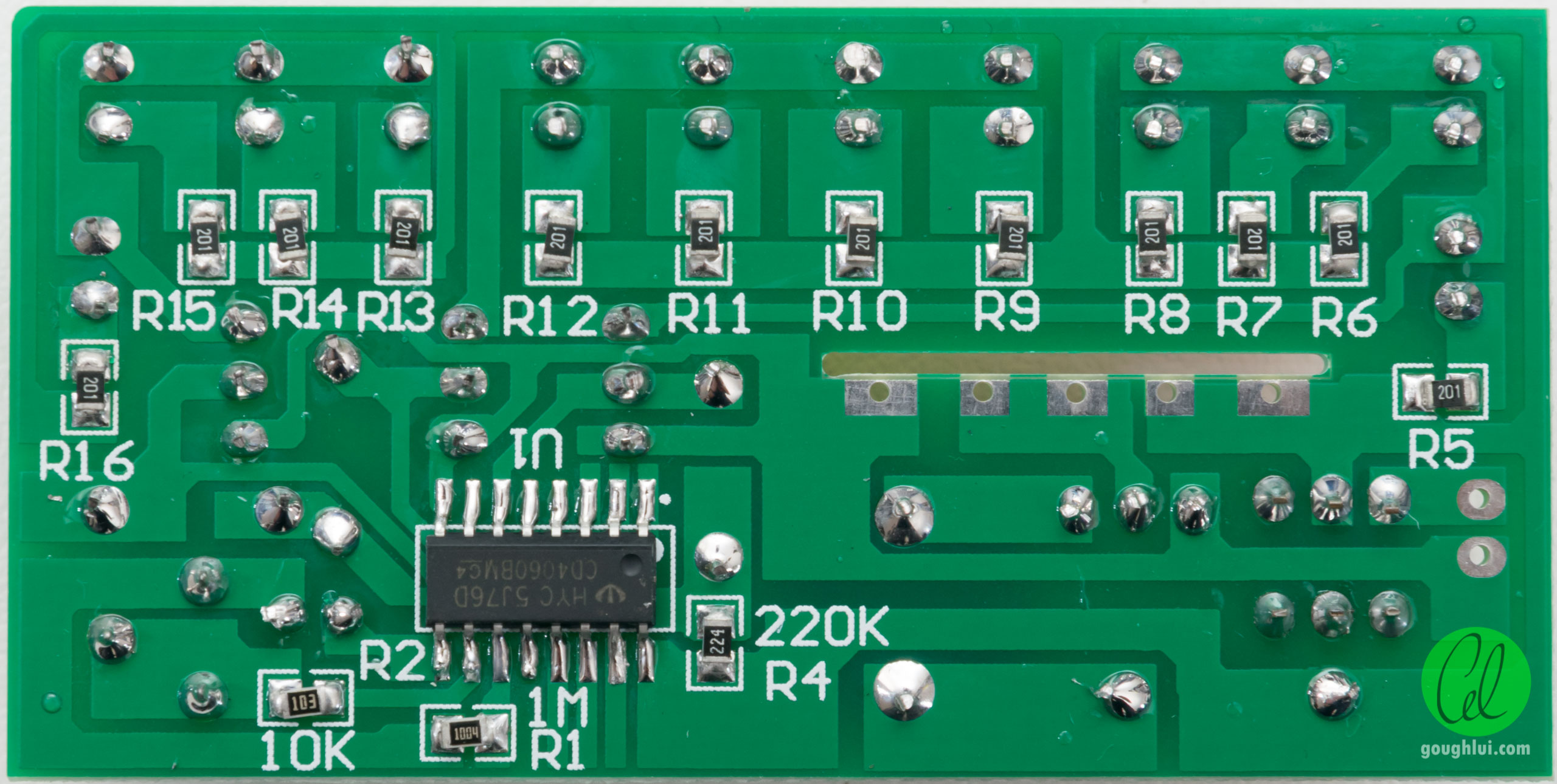
The board is single-sided but covered in silkscreen and solder-resist on both sides. On the top, it’s marked HY 1H34595A.

The circuit itself is single-sided, with the traces finished in tin plate. The tracks are thick in some places and are not soldering optimised, with the soldermask defining the edges of the donuts instead. Despite the sparse soldermask markings and lack of instructions, it is still possible to determine the connections by a process of elimination.


A chip-on-board assembly is provided with a gob top. This is marked with YX015A, although its pin-out is unclear. From what I can tell, this is probably a clone of the CL9300A.
Construction
We begin with a quick computation of the number of joints necessary to complete the kit:
12 LEDs - 24
16 Resistors - 32
CD4060 - 16
4 Transistors - 12
4 Diodes - 8
Speaker - 2
Switch - 6
Trimpot - 3
Power - 2
Chip-on-Board - 5
TOTAL - 110 joints
As this kit is SMD-based, construction starts differently. Not having any solder-paste or stencils, I decided to pre-tin the pads for the resistors first.

This was not a good idea – in fact, I got too much solder onto the pads, resulting in this rather ugly looking result when I used tweezers to place each resistor and run over it with a hot air gun.

Resistors were skewed everywhere, but at least, electrically they make contact. The next step for me was to install the CD4060. Since the pin pitch is not too narrow, I decided to solder this by hand instead.

With a steady hand and a slight excess of solder, I managed to get it onto the board in a decent way.

Finally, all the through-hole components can then go in and get soldered down – nothing too fancy about this, although I left the chip-on-board to the last step.
At this point, we need to install U2, the chip-on-board module. At this point, you should probably stop following the instructions as this is where things start to go wrong.

It was my assumption given the “slot” shape in the board and the fact the card slides neatly and snugly into it, that we are expected to mount the card in alignment with the traces underneath and solder into place.

As a result, that is exactly what I did …

Through careful placement of “fillets” of solder, it was possible to connect the pattern on the PCB to the card without the use of wires.

In retrospect, I should have probably paid more attention to the patterns, as it becomes clear that this arrangement shorts Vcc to a number of the pins … resulting in bad results!
In the end, there was one spare 10k resistor. The lack of spare SMD resistors for other values is definitely not optimal, as they can easily “ping” across the room, never to be found again. No header-pins or connection blocks were supplied for the power input – so you’ll need to solder your own in.
Running the Kit
I applied 5V to the kit and to my surprise, within a matter of seconds, I heard a pop and let out some magic smoke. It seems the music module and the associated 9013 transistor was toast – the way I had connected the module shorted its base to Vcc which led to sufficient current flow to kill the 9013. I suspect the output of the chip-on-board was also shorted to Vcc resulting in its demise as well.
This was all because I took the assumption that the board would go through the slot and connecting corresponding pads would be sufficient to make it work. On closer examination, it doesn’t because the patterns together would short certain elements out. Had I taken the time to trace the schematic out, I would have realised this and perhaps saved the module.
It may have also been further exacerbated by the fact there was no indication as to supply voltage – other sources seem to claim 3V to be the intended supply and 5V may have been a little much for it too.
Regardless, I am left with a kit which flashes banks of four LEDs in a particular binary pattern … the CD4060 part still continues to work.

It was at this point that I traced the schematic out to find that there is no reverse polarity protection for the design (the diode is in the wrong place for that), the music module operates in parallel and independently of the light show (needing just three connections – two for power and one to drive the base of the transistor), and the CD4060 is just driving the LED transistors with three outputs from its self-resetting ripple counter clocked by an R-C circuit. Nothing too spectacular there.
Conclusion
Unfortunately, this kit is the first example in the series of kits I’ve built where a lack of instructions has led to assumptions that let out the magic smoke. As a result, the “musical” LED fancy lantern of mine … is no longer musical and I feel a little sad that I was the cause smoke liberation. After all, my house is a no smoking zone.
That being said, once I drew the schematic and understood what was happening, the kit itself proved to be rather uninspiringly simple. In fact, the music module is “separate” and runs in parallel with no interaction to the light display. The light display uses the CD4060 as a self-resetting counter, with three counter bits driving three banks of four LEDs based on an R-C controlled cycle time.
Aside from that, the PCB itself was of a very average single-sided design, manufactured with decent quality. Perhaps the SMD resistor and CD4060 part of the kit makes for their own challenges which makes this a worthwhile kit to attempt for that reason alone, along with the low price. But in the end, I suppose the lack of music isn’t so bad – it’s probably rather dreadful “noise” anyway, coming from a buzzer-speaker … as a result, I don’t feel it necessary to get another and try again.