

It’s been a while since my last power bank review, so I thought I might as well get one in. The difference is that there is a bit of a story behind this one – it’s probably not a power bank you will encounter frequently, at least, not with this branding.
The Unit and its Provenance
Longtime readers will know that I recently returned from South Korea. When I landed there, one of the first things I purchased was …
… no, not a power bank. But a transportation card, called a T-money card. At the airport, however, they don’t sell regular T-money cards, and instead sell a slightly more expensive (about US$1-2 more expensive) Korea Tour Card branded T-money card.


How does this card differ from an ordinary T-money card? It comes with a fold-out leaflet with subway maps, but also promotional offers from the major shopping malls and tourist attractions … one of which caught my eye …

You read that right – a free power bank was on offer at I’Park mall at Yongsan. Seeing that Yongsan was the home of the electronics market in Seoul, it was a place I was going to visit anyway, so no harm getting a free power bank, right?
As it turns out, it wasn’t so easy to find the refund desk where it could be claimed – and it was subject to stock availability which was claimed to be limited. Putting on my best face, I approached a staff member, which eventually pointed me in the right direction, and I sheepishly asked for one. They went into the back, rummaged a bit, and came out with one of these …
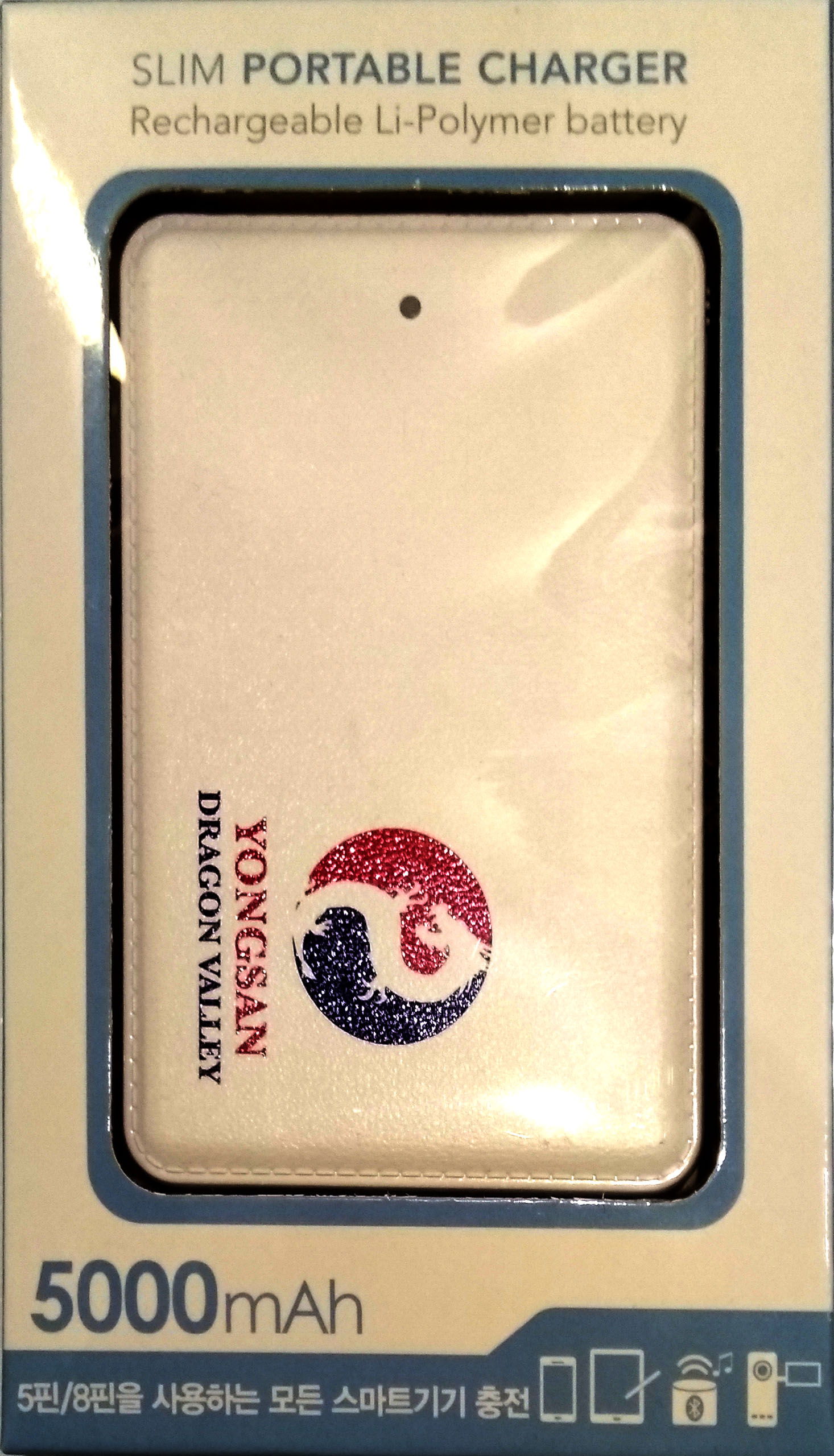

Apologies for the really off white-balance – this was shot “on location” in a budget hotel in Seoul with a mobile phone camera. On a side note, it was raining quite hard that day, so I never did end up visiting the electronics market in Yongsan :(. Maybe next time.
Regardless, this was a slim power bank branded with Yongsan (the locality where I was), and Dragon Valley (the English translation of the name, although it might be better called Dragon Mountain?). Anyhow, the unit was Made in China, claims a capacity of 5000mAh with a current capacity of 1A output and 1A input. There is an AIG logo, but to whom that belongs, I am none the wiser.

The unit is about the size of a 7mm 2.5″ laptop hard drive, and comes with an input cable for charging. The output is a fixed piece of short flat cable terminating in a microUSB-B connector. Indication is via a single blue LED through a translucent window on the front of the case with blink-codes to indicate capacity remaining or charging progress.

 The rear side has a bit of warning text and logos. The surface behind the power bank is actually the hotel minibar fridge …
So, lets say you’re an Apple user – well you might be in luck as there’s a microUSB-B to Lightning adapter included. Whether this actually works, or is it defeated by iOS’ Lightning DRM stupidity, I do not know. But if it does work, it’s a very handy adapter to have just on its own.
Teardown
I did use this unit a few times while I was in Korea just for the novelty value, and bought it all the way back to Australia where further examination occurred. The top cover and the rear are clipped together, and with mild force in the right place, can be separated.

The unit has a fairly small PCB in charge of the power conversion. It’s dated Week 52 of 2015. The output goes to two solder pads with the output wires directly soldered to it. The output wires are enamelled copper wire, similar to headphone wires – I’m not sure such flimsy insulation should be trusted with power output, where some abrasion could easily wear through the coating, causing a short which could liberate a few amps and cause lots of heating (which would, ironically, further destroy the insulation).

A closer look at the PCB shows that it uses an ETA9650 synchronous boost controller IC, which appears to be a 4.35V charge-termination voltage version of the ETA9640. This controller claims to not require an external DW01 for protection of the lithium cell and avoids lock-out by the protection, as an “all integrated” solution with (approximately) 90% efficiency at 1A using a 2.2uH inductor (varying depending on voltage in and current out).
It is surrounded by U3 and U4 which are 8205 MOSFET packages, and U2 which is an unidentified chip marked 7071C.

The rear is not populated, although with a few “splodge” points for tacking wires to. That’s helpful. The coded text is marked WTB-W0505-1A-ETA9650-V01-C.

Despite taking the effort to carefully peel the Li-Poly cell from the enclosure, we are not rewarded with any markings to suggest what the capacity or manufacturer of the cell is. I don’t expect miracles, in this case.
Test Results
Because this power bank is different to every other I’ve tested thus far in not having a USB A receptacle, I cannot test it with my resistive load bank as I had used in the past. But, seeing as I do have a BK Precision 8600 DC Electronic Load, there’s no reason to use the resistive load anyway!

Instead of fighting with the microB connector at the end of the cable, and giving the power bank a slight benefit of not having the cable voltage drop included in the measurement, I clipped onto the input shell (common ground) and the output pad. This avoided potential for moving test clips shorting out the unit.
As this was a “promotional” unit, and getting the connections made was quite hasslesome, I decided to just do a single run-down test at 1A – after all, 1A is about the minimum you’d need to satisfy modern phones, with many capable of sinking even higher currents. Testing was performed with the Battery Test Software provided by BK Precision, under the Sequence Test Program feature.

The result shows the output voltage was quite acceptable until the last part of the test where it declined significantly as the cell emptied. The delivered energy was 12.3405Wh, or about 3335mAh in 3.7V terms. If the cell was 5000mAh, the conversion circuit only delivered 66.7% efficiency. During discharge, the inductor did get quite hot (80 degrees C+), so maybe while the datasheet claims a high level of efficiency, the small open sided inductor used may have had too high of a DC winding resistance or isn’t optimized for operating at the high frequencies used by this chip and thus efficiency suffered.
I monitored its charging with a Keweisi USB Tester, and it was seen that it was able to draw 1A from the source quite consistently. The unit drew an indicated 3643mAh at 5V over 4 hours and 34 minutes, which comes out to about 4922mAh at 3.7V. However, it’s unlikely that the cell was even this capacity, as again, the inductor was very hot during charging implying energy loss. As a result, the true cell capacity is probably somewhere close to 4000-4200mAh at a guess.

The ripple figures were quite interesting – an average peak to peak of 14.65mV is very low. The fact that this is done with the electronic DC load must be remembered, as the previous resistive load was also very inductive (as it was made with wire-wound resistances), thus any AC component in the waveform would likely cause the inductance to “ring along” with it, amplifying the measured ripple voltage.

Zooming in, the ripple was at a fairly impressive 1.942Mhz, matching the datasheet expectation. At least this implies the unit was safe for use at 1A loading, although what happens when the unit is run slightly overloaded was not examined.
Conclusion
Well, if there’s one thing you can’t beat, it’s free stuff. Sure, I might have paid a little more for my transport card, but in return, I got a functional power bank that would definitely work in an emergency. Internally, it uses an all-integrated solution, and while its efficiency seems a little poor and the cell is a bit under-sized, the output was sufficiently stable. Not a bad effort for free.