

Updated [7th Jan 2019] – Error in interpreting noise values due to oscilloscope 10:1 probe setting which I had missed has been fixed.
—
It seems I’ve been using the excuse of Christmas Sales to justify my recent increased spending appetite, but let’s just say that the gifts I buy myself aren’t the normal gifts most people think of when it comes to Christmas. I mean, who buys a high-voltage differential probe for Christmas, let alone two?
For those who don’t already know, a high-voltage differential probe is a special piece of hardware that is often used with oscilloscope inputs to measure high voltages safely. It is an “active” probe, requiring power to run its circuitry, and is capable of scaling down high voltages to inputs safe for an oscilloscope as well as being truly differential (i.e. not directly referenced to ground) with a very high input impedance, so making connections to mains safer and less ElectroBOOM-ey. Definitely a good idea to have one if working around mains or high voltages with an oscilloscope.
Unboxing and Features: EEVBlog HVP-70
Thanks to a posting by a satisfied forum member that previously purchased an HVP-70, I was alerted to a sale that EEVBlog Dave was running on his site that dropped the price of the HVP-70 from $465 to $299 ex. GST and delivery. The main attraction is that the HVP-70 comes from Sapphire, a company that also makes the differential probes for big-name brands such as Keysight and Lecroy. As a result, the HVP-70 should have rather dependable specifications and performance. The total price was $335.18 including GST and delivery – so let’s see what we get.

The unit is packaged in a plain brown cardboard box with a few labels on it. It seems Dave Jones promises no bovine excrement in the package and I’m delighted to report that this does seem to be the case.

Once opened, we are greeted by a plain black and white user manual. Truly no-frills – but that’s all fine by me.

Below the top cardboard tray is the unit itself, wrapped in a rubber protective skin, along with probe hooks, an adjustment tool, Energizer AA alkaline batteries and a silica gel desiccant packet.


The unit itself looks rather industrious and square, with the only bit of roundness provided by the rubber protective skin. EEVBlog’s logo adorns the front label, along with some rather old-fashioned slide switches, a bi-colour power LED and a recessed offset adjustment potentiometer. The BNC cable exits from the top, with the probe wires exiting from the bottom. The rear of the skin features a serial number label and a hole for easier “extraction” of the unit from the skin.

The side of the skin has a cut-out for a barrel plug for external power – on the skin, 9V at 80mA with positive centre tip is the preference.

Each of the probe wires ends in a detachable shrouded banana plug which is inserted into appropriately rated test hook assemblies.

It’s nice to see the output connected through a thick grey coaxial cable, terminating in a BNC plug.

Four Energizer AA OEM batteries are provided, allowing you to get started immediately which is a nice touch. Also included is a small plastic tool for adjusting the trimmer for offset – although I personally chose not to touch the adjustment because often the factory calibration is often good enough.

Once de-skinned, we see slightly different advice for the power input jack – 6V or 9V is acceptable.

De-skinning the device is something you might have to do regularly as the battery compartment is only accessible once the unit has been removed.

The four AA batteries fit tightly into the compartment, with the output BNC cable snaking through the middle.


I have the feeling that the unit has been assembled with care by a few proud people, owing to the labels inside the battery compartment. Rather neat.


The unit weighs an impressive 474g with the batteries and protective case fitted. Just the bare unit with no batteries weighs 275g.
The unit is CAT III safety rated, capable of handling inputs up to 1000V, although only with a linear range of 700V. Two attenuation ratios of x10 and x100 are provided, which are nice round numbers many oscilloscopes have a default probe setting for. The unit features 70Mhz bandwidth (5ns rise time) with 1% accuracy with an output swing of ±7V, offset of ±5mV and 2mV RMS noise typical. The loading is 4MΩ in parallel with 5.5pF to ground on each side.
Unboxing and Features: Micsig DP10013
The purchase of the Micsig DP10013 was a rather “unplanned” affair. In fact, I was intent on grabbing another HVP-70 but they had run out at the time I came up with the idea that I needed two. So, I decided to go on eBay and see what was on offer – to my surprise, Micsig was offering an even cheaper option that seemed to have decent-enough specs that I would consider buying it. It wasn’t a brand I recognised, but it was definitely a niche product so I didn’t have many choices. After stacking on a number of discounts (15% off & $100 gift card at 5% off), I managed to get my unit for AU$154.67 including postage and taxes – practically half the price of the EEVBlog HVP-70. But would it be any good?

From the outside, we see a plain cardboard box with a label on it. It looks rather similar, but is it also free of bovine excreta?

That’s a surprise. No, it’s not a first aid kit – but it certainly looks like one. Being packed in a hard plastic case does seem to be a nice touch, but it makes you wonder just how much money goes into the equipment when the package is so posh.

The surprises continue inside – while the leaflet is just a folded single page and the warranty card shows the unit was sold a little prior to when I purchased it, the kit is surprisingly well packed in foam with a decent number of parts included.

Of course, the probe itself is nestled underneath the manual and warranty card. Rather unfortunately, while the packaging looks good, the functionality is slightly impeded by the fact that the foam parts are actually made of several pieces of foam glued together, with some parts not fitting in perfectly, leaving glue residue on cables in my case.


The unit looks rather cleanly labelled, with just two translucent touch-keys for selecting the range with a green LED underneath each to indicate selection or over-range. Internally, it seems that relays are used to change between ranges, as an audible click results from each range change. No further adjustments or power switches are provided. In fact, the unit is so clean, there are no compartments or screw holes to be found.

That is because this unit relies on USB as its source of power. This is quite a convenience, as USB is ubiquitous and supplied even by some oscilloscopes. The downside is that if the unit fails, maybe it could toast a USB port. Another issue is the power quality of the USB port may affect the performance of the unit. Thirdly, while there is a pass-through USB-A port, the data wires do not appear to be connected, thus it is not possible to preserve USB data capabilities (e.g. saving screenshots to flash drives) while the unit is connected. I suppose if you have a decent power bank, that could serve as a good rechargeable battery to power it – I used my Anker PowerCore+ 10050mAh power bank for the purposes of this review.

While the unit is CAT II safety rated, the input leads are relatively thick and silicone covered, with a CAT III rating of 1000V and a CAT IV rating of 600V providing some margin of safety. The output is a shrouded BNC connector, which might be nice for covering the ground part of the plug, but is led in a relatively thin coax that is somewhat easily kinked.

Of course, a regular USB-A to B lead is provided for powering the unit.

The supplied variety of probes is rather useful and well appreciated. Insulated clips, shrouded probes which are “banana compatible” as well as high voltage “hooks” are supplied, making it rather versatile. I’m beginning to wonder just what’s inside the unit … given the inclusions. But for safety, I will not be pulling it apart.

The whole unit weighs 208g without the USB-A to B lead. Unlike the HVP-70, there are no batteries within the unit, nor is there a protective rubber case – although the provision of the carry case does make this less of an issue.
The unit is CAT II safety rated, less than that of the HVP-70 but still sufficient for working at appliance level. It is capable of handling inputs up to 1300V. Two attenuation ratios of x50 and x500 are provided, which are less common values and result in a lower output swing of ±3V which may not be as optimal depending on your oscilloscope inputs. The unit features 100Mhz bandwidth (35ns rise time) with 2% accuracy (lower than HVP-70’s 1%) with <=40/230mV RMS noise after scaling, which would correspond to 0.8/0.46mV RMS respectively. The loading is 5MΩ in parallel with 2pF to ground on each side, which should mean less disturbance to the device under test. The offset voltage is not specified.
Testing: Input Impedance
One key parameter of differential probes is the input impedance. High impedances translate into lower loads on the circuit under testing, which should reduce the burden of the test equipment on the circuit being tested. It also reduces the current which flows through the test connections, contributing to a factor of safety.


The HVP-70 claims 4MΩ to ground or 8MΩ between terminals. Tested with the Keysight U1461A, it very much complies to the claimed specifications.


Repeating the test for the DP10013, the claimed 5MΩ to ground or 10MΩ between terminals was also measured and confirmed. The DP10013 does have a higher impedance than the HVP-70, which could be preferable under some circumstances.
Testing: Warm-Up Behaviour and Offset Voltage
Warm-up behaviour and offset was judged by shorting the input terminals of the differential probe together while connected to a Keithley Model 2110 5.5-digit digital multimeter for logging. The multimeter had been warmed up for at least an hour prior to turning on the differential probe at time zero. It is noted that the multimeter has an input impedance of 10MΩ, greater than the 1MΩ which most oscilloscopes have, thus the results could differ slightly.

On warm-up behaviour, it seems that the HVP-70 warm-up drift is relatively small overall and reaches equilibrium consistently quickly. At the x10 setting, the reading noise seems to be quite visible, varying in about a 1mV window.
The DP10013 on x50 seems to take a longer time to reach equilibrium with a significant movement of the baseline. The noise appears to be smaller than that of the HVP-70, because the attenuation ratio is higher, so we can’t tell much about that. At the x500 setting, this seems to be less severe.
Of the two, the DP10013 has the lower absolute zero offset voltages without taking the scaling into account. However, even the HVP-70 in its default state has an offset voltage of no more than about 1mV anyway at the x10 setting, comparable to the reading noise level and unlikely to be observed by an oscilloscope input (which typically has less voltage resolution).
Testing: Reading Error/Linearity
Reading error and linearity was tested on the most sensitive range (x10 for HVP-70 and x50 on DP10013). The input to the differential probe was generated using three channels of my Rohde & Schwarz HMP4040 programmable power supply, offering a range of 0-96V which was used for the DP10013 and 0-70V for the HVP-70. Voltages were generated at 10mV intervals, with 16-readings averaged of the actual applied voltage and measured probe output from the Keithley Model 2110 5.5-digit DMM. It is known from my previous review of the HMP4040 that the output was within 1-3mV error of the requested voltage. The DMM measured values were scaled by the probe attenuation factor to determine the “actual” read voltage and the read-back voltage from the power supply was subtracted from this to find the error.

When looking at the absolute graph, accounting for the read-back error from the Keithley Model 2110, the results show that the HVP-70 has a noticeably lower read-back error compared to that of the DP10013. In fact, it seems the DP10013 has a gain factor error with its almost constant slope, reaching about 1.32V error on 96V in (~1.4%). The HVP-70 appears to be somewhat better calibrated, although with a curve but remaining pretty much no further than 150mV from the actual expected value.

As a percentage error, we see that the error at below about 2V escalates mainly due to offset error. Above this, the DP10013 tends to stay stable at many voltages at about 1.4% error, with the HVP-70 achieving closer to 0.45% peak error. Both are within their 2% and 1% claimed error, respectively.
Testing: Noise on Oscilloscope
I decided to give the probes a test on the oscilloscope just to see what their noise characteristics are like. For this, I used a Rohde & Schwarz RTM3004 with its excellent quality inputs. C1 is connected to the R&S RT-ZP10 probe, a classic 10:1 passive probe. C2 is connected to the DP10013 and C3 is connected to the HVP-70.

With the probes powered down, the channels average peak-to-peak noise is relatively close at 12, 9 and 9mV respectively, with the mean level being -2mV, 0mV and -1mV (with inputs as 10:1).

In the x10/x50/x10 ranges, the output peak-to-peak noise is 19, 61 and 104mV respectively with a mean level of -3, -8 and -10mV (with inputs as 10:1). When scaled, the effective noise level referenced to the input is 19, 305 and 104mV respectively, thus making the HVP-70 less noisy than the DP10013, although not as quiet as a passive probe (as expected).

In the x10/x500/x100 ranges, the output peak-to-peak noise is 12, 21 and 38mV respectively, with a mean level of -3, -4 and 2mV (with inputs as 10:1). When scaled, the effective noise level referenced to the input is 120, 1050 and 380mV respectively, thus again confirming the HVP-70 is less noisy than the DP10013 when used with the RTM3004 once the scaling factor is accounted for.
Testing: Different Waveforms and Skew
Not having much high voltage stuff around, there’s not much in the way of waveforms I can test. However, I did have some in mind I wanted to check – for example, this modified sine wave inverter …

… which, as expected, is just a fancy name for a rectangular wave with dead-time. That being said, the results from all three probes coincided mostly, with the HVP-70 reporting a little lower on the voltage while the DP10013 was a little high.

Looking at the rise of the square wave, all three probes coincided very well.

To be a little evil, I decided to use a leading edge dimmer with an incandescent load – these normally produce quite sharp transitions – in this case, all three show practically the same waveform (visually speaking), so I’m fairly happy with that.

I thought I might as well test the pure sine wave inverter as well – as noted before, the HVP-70 seems to read slightly below on the voltage, whereas the DP10013 reads slightly high.
To test the skew between probes, I decided to probe the output of my inverter through a switch. Once the switch is thrown, in theory, all channels should rise at exactly the same time and rate. However, due to the propagation delays through an active probe, the time will be offset and if phase alignment is critical, deskewing the probe will be necessary.

The raw skewing data suggests the DP10013 was behind the passive probe by 2.6ns, whereas the HVP-70 was behind by about 7.7ns. This is a very tiny amount that you probably won’t need to compensate for – the above graphs don’t show any noticeable offsets for their timescales.

However, it seems I might have been a bit pessimistic about the HVP-70’s delay – playing with the skew figures in the limited increments provided in the RTM3004, I found -2.8ns and -5.6ns to cause the switched input curves to best coincide – the reason may be due to the slower rise time of the HVP-70, thus I was looking into the slew rate limit rather than the actual point the input rose above the 200V threshold.
Testing: Power Consumption
Testing power consumption was done by using the R&S HMP4040 to supply power. In the case of the HVP-70, power was supplied directly to the battery terminals through a set of alligator clips. At an input of 4.3V, the bicolour LED flashes to indicate low battery and the unit consumes 186mA, failing by the time it drops to 4.2V drawing 114mA. At an input of 5V, it draws 157mA; at 6V, it draws 157mA and at 9V, it draws 97mA. As a result, it seems amenable to adapting for USB power input (if you wish) and its behaviour suggests it does use an internal boost regulator to ensure stable voltage swings can be achieved despite varying battery voltage.
Power consumption for the DP10013 is probably a little less important since it doesn’t have its own internal battery. In my measurements using the HMP4040 to supply power, it consumed about 185mA at 5V. This is slightly higher than the HVP-70 unit and might have something to do with the power consumption of the internal relay coils. Input voltage down to about 3.5V was tolerated before it would malfunction and relay changes would not occur during an input change. The LEDs do dim a lot even before we reach such a low voltage and it is not guaranteed that the probe will register the correct readings at such a low voltage. The DP10013 is somewhat sensitive to the input power – as I noticed when plugging in a downstream USB device, it caused a slight shift in the output trace on the oscilloscope.
In-Use: Fluorescent Tube Starting
So how might one actually use one to explore higher voltages with an oscilloscope? I’ve always been fascinated by the old “inductive” control gear based fluorescent lamps with the old fashioned bimetallic-strip based glow-starter – you know, the ones that go “brrrr – tink – tink – tinktink” before they come on.
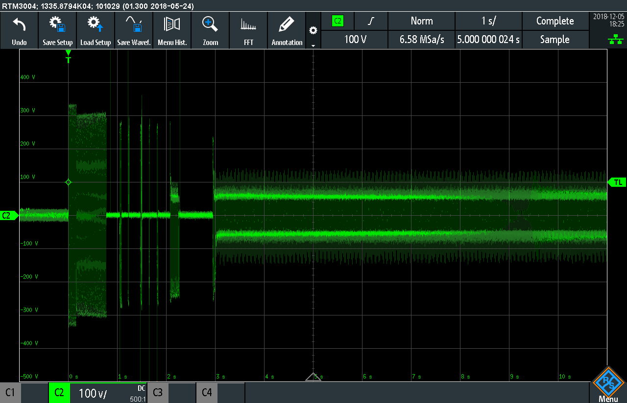
Using the DP10013 connected across an 18W fluorescent desk lamp, we can observe the voltage across the tube during the start procedure. Initially, when the power is switched on, the full line voltage appears across the tube but nothing really happens since the gas is not ionised. Instead, the tube starter begins drawing current through its internal discharge, warming the bimetallic strips inside. At one point, the strip warms enough that it shorts (the voltage across the tube falls to nearly zero), thus saturating the inductor, warming the filaments in the tube to improve their thermionic emission abilities and allowing the strip to begin cooling. Once the strip opens, a short spike (the inductive kick) is seen which sometimes ionises the gas in the tube allowing it to run. A few attempts are needed before it runs – as we can see in the above trace, and at one stage, it seems the tube was acting a bit like a rectifier as one of the filaments may not have gotten warm enough.

The inductive kick, looking at a number of traces, for a short 18W tube seems to reach 450V peak-to-peak, which is surprising as the running voltage is significantly less.

While the tube is running, the RMS voltage is just 57V, and the waveform takes on an almost square form despite the sine wave mains power coming in. This is due to the negative-resistance characteristic of the tube interacting with the inductor’s reactance.

In one capture, I saw the exact point where the tube decided to start running – the first few cycles are unstable, before it runs smoothly with the waveform above. Neat, and something I did not know!
Conclusion
The two differential probes reviewed performed as expected based on their paper specifications in the testing. They have slightly different designs and operational parameters which can affect their suitability for certain uses.
In the end, rather surprisingly, I’d have to give a very slight preference to the cheaper Micsig DP10013. For a lower price, it definitely gets the job done with less loading/greater input impedance compared to the HVP-70, a higher claimed frequency response, more bundled accessories and a nicer push-button/LED interface. The downside is the higher noise level, reliance on USB power connection, a slightly slower warm-up performance, lower voltage output level, lower tested gain accuracy and the lower CAT II safety rating. These are not big downsides if you already have a decent power bank, are willing to wait the required warm-up time, don’t have a high-performance oscilloscope or don’t need very fine voltage accuracy and are not working on switchboards or low-impedance mains supplies. The bigger issue may be with the output voltage levels, as the observed noise on the oscilloscope will depend on how your oscilloscope input ranges compare with the output voltages generated from the DP10013. Being attached to a rather “quiet” RTM3004, the DP10013 still exhibited higher noise than the HVP-70 which could be worse depending on what your oscilloscope is like at resolving lower voltage levels.
While the EEVBlog HVP-70 might be a bit more expensive, I don’t regret my purchase either, as the CAT III rating and Sapphire heritage gives me a little more confidence in its performance, with the AA self-powered arrangement being convenient where cable clutter needs to be minimised. The ruggedized rubber surround also makes it a little more durable. The slightly lower input impedance doesn’t ordinarily impact on my work either, while the x10/x100 ranges are commonly pre-set into oscilloscope inputs, making it quicker to set-up. The coax cable on the unit is also slightly more robust and the noise and accuracy performance is noticeably better. While it appears rather old-fashioned in design, it does exude confidence that the design has been proven over time and a reliable workhorse for serious applications.
While others may be inclined to chance using an oscilloscope to analyse mains signals with 10x probes – it’s not a good idea and it puts the oscilloscope and the user at potential risk. Given the reasonable price of the high-voltage differential probes tested, it makes good sense to invest in one.
Hi Lui,
Thanks for your beaut review of these high-voltage differential probes.
Although I’m very interested in using a differential probe with my oscilloscope, my application is at the opposite end of the scale (low voltages, rather than high voltages). Specifically, I want to do ‘safe’ measurements on Arduino-based circuits without directly referencing ground.
Two possibilities that on the surface seem most likely to be suitable are these:
Pintek DP-30HS 1mV – 65V High Sensitivity Differential Probe, 30MHz
Pintek DP-40LV 10mV – 650V Differential Probe, 40MHz
Here’s a link to the manual for these two models:
http://www.pintek.com.tw/files/pintek/DP-30HS-40LV-MANUAL.pdf
I appreciate that you likely have no personal experience of these probes and am certainly not looking for any type of a recommendation.
However, perhaps you’d be prepared to tell me if they seem like the sort of thing I should be after… or am I entirely on the wrong track?
I’d be most grateful if you’d be willing to do a quick flick through the (brief) manual and give me your opinion.
Cheers
Ric
Dear Ric,
Unfortunately, I’d have to say I don’t have experience with such probes although (funnily enough) I am also in the process of considering whether it is something I should also have. For some truly differential low voltage signals, it is something which seems appropriate to have where one leg definitely cannot be referenced to ground in any way and if you want/need to preserve a limited number of data acquisition channels.
On the whole, many measurements at low voltages can be made safely with passive probes, short of bandwidth issues when attempting to measure very low voltages. Most oscilloscope inputs are 1Mohm, adding probe resistance if using x10 probes brings this to a healthy 10M or thereabouts. If you have sufficient channels, you could potentially try putting one input into Channel A, another into Channel B and use the math subtract function, leaving the grounds unconnected (and leakages to find some path through the internal scope impedance). Otherwise, maybe better planning of the probing of the circuit could allow for one ground reference to be chosen in some cases. Otherwise maybe building an opamp based differential amplifier could also do the job depending on what accuracy/bandwidth requirements are.
The issue of ground reference is a bit tricky. Many probes will have a high impedance to ground so as not to be completely isolated as part of their design and due to the oscilloscope in question. In the case of the high voltage differential probes, that’s 4M or 5Mohm to ground. In fact, the DP-30HS/DP-40LV you linked appears to have a 1Mohm impedance to ground from either terminal. While this gives you true differential ability, it’s something to be aware of – it’s not “truly” free of leakage currents. Ideally, if you really need isolation (e.g. for medical reasons), then something with an analog optoisolator/optocoupler or a transformer-based isolation is necessary to ensure proper isolation.
One hack that I’ve often used where I need no ground is to use a USB-based oscilloscope on a laptop without any other devices or power adapter connected. This should leave the laptop “floating” – at low voltages, this is unlikely to cause any safety issues. Another thing others do is either defeat the ground pin on your oscilloscope power lead or run it from an isolation transformer, but both present significant safety issues so I cannot recommend doing that.
As for the performance of the units – it’s very much something you’ll just have to test. Unfortunately, with such niche test equipment, there aren’t many people who would seek such equipment or have tested them.
– Gough
Dear Gough,
Thanks a lot for your prompt and most helpful reply. Several really good ideas for me to consider.
I especially appreciated your suggestions about using an opto-isolator or a usb-based oscilloscope connected to a floating laptop –makes so much sense.
It would be most interesting to read about any explorations you make into the area of high sensitivity/low voltage differential probes if you choose to follow up that issue in the future.
Cheers
Ric
Hello Gough,
Thanks a lot for your personnal review of both probes.
I’m surprised by the results of the noise measurements as they seem to be far away from the specifications of the probes (ie the DP10013 is specified at less than 40mV rms in x50, and you measure 400mVrms with respect to the inputs, similarly the HVP70 displays a x10 deviation with respect to the specifications )
I believe you might have chained the x10 scaling of the scope with manual scaling afterwards, thus reporting 10 times higher noise levels.
regards,
Nicolas
Thanks for that – well observed and indeed that was the case. I thought I had turned off the 10:1 probe setting but evidently it shows up as being switched on. I am in the process of correcting the results as we speak.
– Gough
Excellent review, thanks for the unbiased advice and thorough testing of both active and passive probes! Will be back to read more reviews at a later time! Keep up the good work!