

Over the years, I’ve pursued my curiosity through running experiments of my own, enabled by a suite of test equipment that I have carefully curated over the years. Being a major beneficiary of the element14 RoadTest program and the generosity of a number of companies, I’ve been fortunate to be the owner of precision equipment which I couldn’t otherwise justify purchasing just for my hobby.
Increasingly, as I built up my skills in automating test workflows to gain insights into seemingly simple things such as batteries and power converters, the power of SCPI remote control became a key enabler in allowing me to perform fine-grained tests in an unattended way. I couldn’t see myself going back to “twiddling knobs and writing down numbers,” as so many students in labs still seem to do today.
When it comes to instrument connectivity, the rules of thumb have always seemed to be as follows – the use of GPIB is expensive but has perfect synchronisation due to the use of dedicated handshaking lines, while the use of USB is convenient and still fast but limited by a per-cable distance of 5m without the use of hubs. The choice of Ethernet/LXI-LAN would be preferable if intending to share the instrument across many users or when connecting over a distance, but has potential latency and security disadvantages.
As a result, many years ago when I started reviewing instruments, they would get marks for having a variety of interfaces available, but I wouldn’t penalise them for not having Ethernet. I would usually use my instruments connected to my desktop PC, so USB would be just fine.
However, over the years, my sentiment has completely changed and it now seems that Ethernet should be the interface of choice for the modern world. After all, common Ethernet is plenty fast (1Gbit/s is commonplace), ubiquitous, low-cost, can (over copper) reach 100m, connect innumerable numbers of devices together and can be managed through ordinary IP infrastructure (e.g. smart switches, routers, firewalls, VPNs). If one really wanted to, they could even eschew the complexity that is the whole Virtual Instrument Software Architecture (VISA) altogether and just talk to devices like they talk to any other network socket. What was once complex has become simpler – even an Arduino can support Ethernet and Wi-Fi.
Accordingly, most instruments nowadays do come with Ethernet/LXI-LAN and some even with Wi-Fi, while higher performance instruments transcend the limitations of socket, VXI-11 protocols and move to pipelined protocols such as HiSLIP which reduce the latency-induced downsides.
This brings up the obvious question of “What do we do with these pre-LAN instruments?”
My Motivation

Back in late-2013, I RoadTested a Keithley Model 2110 5.5-digit Digital Multimeter. This has been a trusty member of my instrumentation arsenal and is still my most accurate DMM to this day. It’s still in use quite a bit, although the improved integrated monitoring in power supplies (e.g. the Rohde & Schwarz NGM202) has reduced the need for using a dedicated DMM somewhat. It is still very useful for monitoring temperature or for voltage/current monitoring for older supplies with less granular or less accurate metering.
The Model 2110 is quite ordinary for its time with regards to connectivity. Being a “budget” model, the unit is actually a rebranded PicoTest unit which ships with USB-TMC only by default. The slightly more upmarket version (which I have) has an additional GPIB interface. Unfortunately, there is no LAN interface on the unit.
My most recent RoadTest saw the need to employ the DMM for measurements, which meant hooking up the DMM by USB. Normally, I hook the DMM up to my desktop computer and run the scripts there but there’s a few major downsides. As I run Windows 10 on my main workstation, unexpected reboots for updates are a feature that has spoiled some tests before. Other than that, the machine draws quite a bit of power and produces quite a bit of heat even when doing relatively little, which means added expense.
Because of this, ever since I reviewed the Harting MICA Industrial Linux PC platform, I’ve used my review unit as a “test controller”. I would develop my Python scripts on my desktop, load it up to the unit and have it execute on the unit around the clock (while I went about my day’s work and when I was asleep). It is in some ways, quite similar to the Raspberry Pi in being ARM-based, running Linux as an operating system, having USB and Ethernet interfaces.
But because of the layout of my room, there was no way I could connect the DMM into the Harting MICA without causing a major trip hazard or potentially impacting on reliability (longer cables frequently cause issues). Even if I could, the other downside is that then I couldn’t share the DMM with the desktop easily without either unplugging the USB and moving some cables about. There has to be a better way …
Before USB-TMC came GPIB
Because the Keithley Model 2110 had GPIB, I thought I’d explore the GPIB side to see if there is much that can be done with it. As it’s a bit of an older, parallel bus, perhaps there were economical ways of working with it to provide some alternative connectivity.
As it turns out, there was the AR488 Arduino GPIB interface software which would use up practically all the pins on a regular Arduino Uno board. Use of a larger Arduino Mega board would make things more comfortable – perhaps it would be possible to turn GPIB into LAN using an Ethernet shield as well. Finding a compatible connector is a little more challenging – it would cost anywhere from AU$5 to 15 for the connector plus postage, while GPIB cables were just very expensive in general but it was a possibility. It didn’t seem all that expensive overall, but it would be a bit of a gamble to try and get it working. Perhaps if I had a GPIB-only device, that would be a good thing to try.
That project actually emulates the Prologix GPIB-ETHERNET controller which is a commercial product that allowed for bridging the two together and introduced the ++ command set for configuring the converter. One thing I did dislike about these solutions is the fact that configuration might not always be straightforward and the resulting “combination” of equipment could have its own quirks, but perhaps the biggest issue was the price tag – US$199.95 plus postage. Using it to interface to a DMM that isn’t worth more than US$749 when new just doesn’t make sense – best to put that money towards a new Keithley DMM6500 with inbuilt LAN instead.
While digging about, I also came across the ICS Electronics 4865B interface which was an even more eye-watering US$580 plus postage. Evidently, going “backwards” in time to GPIB was probably not the best way to do it.
Existing USB-TMC to Ethernet Bridge Solutions
So instead, I looked towards USB-TMC to Ethernet Bridges. There, I came across the Keysight E5810B which does GPIB, USB and RS-232. It seems quite the nifty device but at a price of AU$2003, it also didn’t make sense for my application.
Instead, using a Raspberry Pi seemed to be a much better idea as it is a commodity item, I had a few old original RPis retired from over four years of active 24/7 service that I could use. Such projects had even been done before! This blog by Mike DePalatis showed how to build a kernel with USB-TMC support and use socat and a Python program called usbtmc_pipe.py to perform the bridge feature. In fact, this appeared promising as the current Raspberry Pi kernels already have USB-TMC support baked in, so grabbing socat and the Python program would only take moments.
Another option was to use this rather widely noted project by Volker Ziemann in 2014 which also uses a Raspberry Pi and kernel-based USB-TMC support with a shell script called talk2scope.sh, cat2.sh and netcat. This particular set-up is designed for use with Arch Linux ARM and the scripts were compiled together by pklaus. While I might have wanted to try this, I didn’t have any experience with Arch Linux ARM and would rather not spend time on that.
Good, but Not Good Enough!
I gave the first project a try with usbtmc_pipe.py and while it did work somewhat, it had some rather annoying limitations. If the USB communications encountered any errors, the server seemed to just crash or hang and would never properly recover. This could be easily induced by causing a timeout error – i.e. by fat-fingering a query command (e.g. FETTC? rather than FETC?). As I like to debug “interactively”, making such mistakes does happen occasionally, and I’d rather not have to physically unplug and replug my USB instrument to recover the functionality.
I didn’t try the second, but looking at talk2scope.sh and its hard-coded 10ms waits after read and 10ms wait after write, it didn’t inspire much confidence regarding its performance and behaviour in case of a read timeout.
I had a bit of a think and wondered if it were best just to eschew the whole complexity of Linux and just build something that would just do the one job and stand up to unexpected power-downs. Investigating the USB-TMC protocol seems to suggest it is not all that complex (assuming you understand USB as a whole). The difficulty was interfacing with USB, which led me to discover the USB Host Shield based on the MAX3421E. Unfortunately, the library code doesn’t have any USB-TMC support as yet but seeing as it’s just some messages with headers riding on a bulk in/out transport with an optional interrupt transport, it shouldn’t be all that different to the USB-CDC code that’s already there. Marry this up with an Ethernet shield and you’re probably almost there … assuming you have enough code space and RAM. But I gave up on this idea since I couldn’t actually obtain one of those shields … so back to the Raspberry Pi it was.
My Crude USB-TMC to Ethernet Bridge
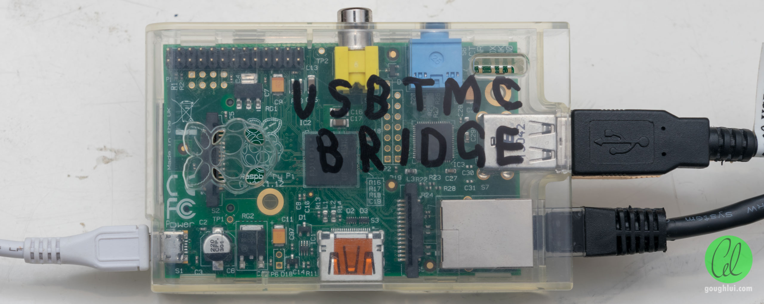
Having now gone full-circle back to USB and Raspberry Pi, I decided to employ an old Pi 1 that I coded to do firewall duties for many years for my university (until I replaced it with a specially-configured Mikrotik hAP mini). I didn’t realise the original Pi is already almost a decade old – this one still in its original clear Multicomp case. The writing? That’s me with a permanent marker on the inside of the clear case, trying to write in a mirrored fashion as best as I could.

Not wanting to have an SD card jutting out of the side that could be knocked off, I have a special SD to microSD adapter that was quite commonly used with original Pi boards, keeping the USB card captive. Sure, there is no need for a 64GB microSD card but that’s what I had free on hand … so I ended up using it. A 4GB card or larger should easily suffice.
The recipe was as follows:
- Grab the latest Raspberry Pi OS Lite, unzip and write the image to a microSD or SD card (4GB or larger).
- Write a file called ssh to the (FAT32) boot partition of the card to enable SSH access for headless set-up. Alternatively for those with Wi-Fi, you may also choose to write a wpa_supplicant.conf file to pre-configure wireless with your network parameters.
- Apply power and wait for the board to boot up – first boot takes quite a few minutes especially on an older Pi such as mine.
- Find the Raspberry Pi on the network (e.g. by scanning the network, looking at your DHCP leases on your router, trying to resolve for hostname ‘raspberrypi’) and login on SSH (pi/raspberry).
- Change the password for the pi user immediately by using passwd
- Configure the settings for the Raspberry Pi using raspi-config. Suggested changes include locale, timezone, GPU memory split (16MB for headless), overclocking (900/950MHz seems safe for older boards), hostname.
- Configure a static IP by editing /etc/dhcpcd.conf and uncommenting/changing the static IP configuration profile lines (optional). I prefer static IP for instruments myself as it avoids potential losses of lease and issues when the DHCP server goes down or gets rebooted (especially if leases are not written to disk).
- Update the software on the Raspberry Pi to the latest versions – sudo apt-get update first, then sudo apt-get upgrade and sudo apt-get dist-upgrade.
- Install the necessary software – in my case, I am going to be using Python 3 but also want screen so I can have things executing even when not connected to a terminal. Do so by using sudo apt-get install python3 python3-pip libusb-dev screen
- Install the necessary Python libraries by using sudo pip3 install pyvisa pyvisa-py pyusb
- Shut down, plug in your USB-TMC instrument and start up the Pi for some tests.
Assuming your installation is all good, trying to list the USB-TMC instruments should give you a response with the resource ID string for your instruments:
import pyvisa
rm = pyvisa.ResourceManager()
rm.list_resources()
If not, then perhaps you did not execute Python 3 with sufficient privileges to communicate with USB devices, don’t have pyusb or libusb installed. But once you see that much, it’s time to develop something to “bridge” Ethernet with USB-TMC.
I opted for a very manual approach, writing a script called k2110-visa-agent (see appendix for the code listing). This program basically uses blocking TCP sockets to create a listener, opens the instrument once it has a socket open, writes commands/queries received to the instrument and returns a reply where necessary. In case it hits an error, it will try to close the instrument and re-open it on the next command which prevents instances of needing to unplug/replug the instrument after a command timeout occurs and allows for a way to regain synchronisation when things go wrong.
At the moment, the code is very basic – there is no automatic configuration, mDNS announcements, VXI-11 protocol support. In fact, the script uses a hard-coded manual resource string and Ethernet bind address/port. It also doesn’t do any checking of the data and likes to abuse global variables. The way it reads the input also means that it cannot handle commands that are broken across multiple TCP packets as it is likely to read in a “sheared” command and send that on – this case is quite unlikely for when operating on LAN as each command is usually sent in a single packet, but cannot be guaranteed when traversing through an SSH tunnel for example. It could be much improved (e.g. by using the logging library for proper logging, by fixing the globals, by creating a parser that handles the data packets as a stream searching for termination characters), but it solves a problem for me as it is.
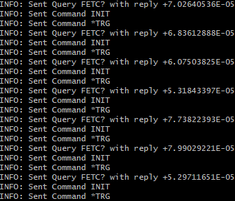
 My first attempt actually did seem to work, but had some curious tendencies. The reading of packets by Python was slow enough that multiple packets were read in at once, so “INIT\n*TRG\nFETC?” became a single query. This still works just fine and has no real downside except for the fact that it just looks odd with the debug printing.
This was easily fixed – by adding code that looked for termination characters to split the data strings. This handles the issue of multiple commands clumped together but does not improve the handling of “sheared” commands across several packets. But it is not entirely necessary and probably degrades performance!
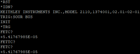
I also tested the error recovery – as expected, it was able to bring the device back to life after a query timeout which is the main feature I wanted from this all along! Note that the screenshots are from an earlier “evolving” version of code, so the printing is a little different to the uploaded version. The reading of the same value is expected as no INIT/*TRG cycle was used so no new reading is taken.

To use the instrument from scripts, I had to change the resource identifier to point to my bridge – in this case, it would be TCPIP0::192.168.80.61::5025::SOCKET but I also have to specify the read termination character – i.e. ins.read_termination=’\n’ or the script will time-out.
From here, it can be possible to perhaps invoke the script(s) automatically using /etc/crontab at each boot using the @reboot command, perhaps wrapping it in a loop so it will automatically restart if it crashes. Perhaps it might be possible to grant enough permissions to the pi user so that the script does not have to be invoked as root and avoid the security issues that come with that. For now, I’m happy enough to start up the box when I need it, SSH in to invoke the script in a screen instance, then Crtl-A, Crtl-D detach out of the screen and disconnect from the box leaving the script running.
Once you are fully happy, it might even be possible to use the overlay filesystem options to make it more robust to loss of power and eliminate writes to the card, assuming you have the configuration fully confirmed, but I did not test this capability.
Performance Test
At last, I have my USB instrument on my LAN in a rather manual way, what is the price for this convenience? I decided to have an instrument race. The Keithley Model 2110 is not a bad contender, as it is capable of 0.001PLC measurements, so theoretically taking 50,000 samples per second into its buffer. But as I’m reading a single measurement at a time using an INIT, *TRG, FETC? cycle, things are a little slower.
The best performance is likely to be directly connected via USB to my main Ryzen 7 1700 8-core workstation running at 3.75GHz with Windows 10 and NI-VISA 20.0.

The inter-sample time is mostly between 2-3ms, so roughly 400Hz sample rate. Not a bad result at all, suggesting it is using USB 2.0 (since USB 1.1 has a 1ms latency for each packet and such times would not be possible given the number of commands involved).

The uploaded code with the debug printing fares noticeably worse – it’s now about 20ms between samples or about 50Hz sample rate. This is still fast-enough in a 50Hz country as most people won’t want to sample below 1PLC if they care about accuracy and rejecting mains-borne interference, but the difference in performance is definitely there.
But knowing that I was connected by SSH and viewing the console output at the time and the printing is blocking and takes time, I commented out all the INFO prints and also took out the code that “segmented” lumped requests (as there can only be performance degradation due to overheads by doing so) …

I was able to double the performance, now with most samples returning in about 10ms or a 100Hz sample rate. It’s still only about a quarter of the sampling rate achievable over USB, but a 10ms sample-to-sample time is quite competitive with some older LAN-based instruments which might take anywhere from 30-120ms to process a command. Nowadays, many LAN instruments are capable of say 5-10ms command times – but this is a batch of three commands and a response, so I think this is excellent considering it is also Python-based running on a Raspberry Pi 1.
Conclusion
When it comes to test equipment connectivity, Ethernet well and truly seems to be the right interface for “now”. Unfortunately, older instruments which don’t natively support Ethernet can be a little more difficult to integrate into a test setup – in my case, the USB cable distance limitation without a hub, potential reliability concerns and the need for instrument sharing meant that I was looking for a way to bridge a USB-TMC device to Ethernet.
Existing commercial products are not cheap, nor widely available. I did consider the possibility of DIY GPIB-based and USB-based solutions based on Arduino and while it may be possible, it just seemed to be quite a bit of development effort.
Instead, I followed along the path that most others have taken – to employ a Raspberry Pi as a bridge. Finding the previous examples reliant on the kernel USB-TMC implementation to be especially deficient in handling instrument timeout conditions and not being able to recover without a physical unplug and replug of the instrument, I decided to write a crude and manual bridge that uses Python 3, pyvisa, pyvisa-py and pyusb to do the job with a little bit more robustness. So far, it seems to work for me despite some known deficiencies and it works pretty quickly as well, achieving 10ms reading-to-reading times over LAN with the Keithley Model 2110 DMM while a directly USB-connected condition achieved around 2.5ms.
You might wonder why I couldn’t just run Python-based scripts on this Pi that is directly connected to the instrument and communicate with the others over LAN. This arrangement would be low-power and avoid the Python LAN bridge induced latency altogether – that is indeed an option I have considered and is yet another reason why having a Raspberry Pi is great as it offers new versatility. The potential downside is having “yet another machine” to login to retrieve results from, or yet another environment where you need to install and upgrade more libraries – I have some other instruments that are Modbus TCP-only, for example and my Harting MICA has already been set-up with the necessary libraries.
But I suppose this is what happens when an engineer faces a problem … they try to build their way out of it!
Bonus – Rohde & Schwarz Launches NGU201/NGU401 SMUs
It was a surprise to me, but just two or so days ago, Rohde & Schwarz officially announced their NGU201 and NGU401 source measurement units. They thus join a relatively small group of companies offering SMUs, including Keithley, Keysight, Yokogawa and ADCMT.
The NGU201 is a single-channel two-quadrant SMU (up to 20V/8A/60W) which is a bit of a departure from the classical use of the term which used to exclusively refer to four-quadrant supplies. This one is particularly aimed at mobile communications testing and seems to build upon the capabilities of the NGM201 which itself is a superset of the NGL201. The datasheet specifications indicate improvements over the NGM201 in a new “current-priority” mode (I presume meaning a “true” current source), increased 8A capability in the 6V range, new low-current ranges (down to 10uA) and improved accuracy specifications. From my point of view, it seems the NGU201 is a superset of the NGM201’s capabilities, which itself is a superset of the NGL201 thus making a good migration path.
The NGU401 is a more interesting beast, being a single-channel four-quadrant SMU with the same kind of power envelope (up to +/-20V/8A/60W). This SMU does come with the ability for modulation input (+/-24V) at up to 1kHz which means it could actually generate AC which would be a rather interesting capability to have. The downside of the modulation capability is that it removes the dedicated DVM mode function from this unit as it uses the pair of terminals normally used for DVM mode. Another interesting quirk is that the NGU401 is stated as not being able to do Constant Resistance sinking and thus, it is not capable of battery emulation mode. It seems more geared towards power-semiconductor testing where this is probably not a major issue, but it does mean that the NGU401 is not a “drop-in” for an NGU201.
Both look very similar to the NGM/NGL201 from the outside, sporting the large touch screen, nearly identical interface (including the graphical view feature) and similar chassis that works on a bench but is also rack-mountable. As with the higher-end specialised supplies, FastLog is on hand to provide 500kS/s logging capability which would be nice for recording data on sweeps or short transients. A key difference is the presence of additional jacks for Earth and Source-LO to facilitate easier grounding connections – a nice touch. I wonder if the internals will be similar as well?
So far, it seems these units are only just beginning to trickle out – no word on local pricing nor on availability but Farnell UK does seem to have some pricing now. Even my local R&S representative doesn’t have a demo unit on hand, but I hope to have a chance to at least give some features a try sometime, perhaps when I get a chance to visit their North Ryde facility here in Sydney.
In the meantime, it seems there is a slim chance you could win one through element14, Newark or Farnell (depending on your geographical location) just by leaving your details and permission for contact (yes please!).
Link to the Australian draw here – https://au.element14.com/rohde-schwarz-ngu
or find the corresponding draw for your country by visiting the banner on the main element14/Newark/Farnell webpage for your country. Good luck!
Appendix: k2110-visa-agent Code
The following is a listing of the k2110-visa-agent.py Python3 script I used to perform the USB-TMC to Ethernet bridge function. It can also be downloaded as a ZIP file. No warranties are provided or implied – in fact, the code has a number of known deficiencies including the inability to handle commands which span multiple packets (which are likely to become “sheared” when the blocking read command returns) and abusing global variables. It may also be “dangerous” and contain vulnerabilities. It does, however, seem to do the job for me in a pinch. The code is free for all to use and modify, provided credit is provided. To use with other instruments and/or configurations you will need to change the VISA resource string, bind address and port. The code relies on Python 3’s pyvisa, pyvisa-py and pyusb when used on the Raspberry Pi and may need to be invoked with superuser privileges depending on your USB device and network port access privileges.
# Gough's Crude USB-TMC Bridge Program V0.1 - Feb 2021 (goughlui.com)
# Developed because I wanted something more robust that would handle instrument
# dropouts and incorrect queries causing timeouts.
# Plus I was sick of my DMM being USB-only since I co-ordinate tests using LAN.
# Downside is no handling commands split across packets (rare on a LAN).
# No warranties or guarantees - modify and use at your own risk!

import pyvisa
import time
import socket
import sys

rm = pyvisa.ResourceManager()
connectstatus = 0

def instrument_connect() :
  global connectstatus
  global ins_k2110
  while True :
    try:
      print("INFO: Attempting to open instrument")
                                    # MODIFY FOR YOUR INSTRUMENT
      ins_k2110 = rm.open_resource("USB0::1510::8464::1374001::0::INSTR")
    except:
      print("WARNING: Failed to open instrument - retrying in 10s")
      time.sleep(10)
    connectstatus=1
    break

def send_string() :
  global connectstatus
  if connectstatus == 0 :
    instrument_connect()
  try:
    ins_k2110.write(data.strip())
  except:
    print("ERROR: Failed on Command Write!")
    instrument_disconnect()
    return
  print("INFO: Sent Command "+str(data.strip()))

def send_query() :
  global connectstatus
  if connectstatus == 0 :
    instrument_connect()
  try:
    reply=ins_k2110.query(data.strip())
    connection.sendall(reply.encode())
  except:
    print("ERROR: Failed on Query!")
    instrument_disconnect()
    return
  print("INFO: Sent Query "+str(data.strip())+" with reply "+reply.strip())

def instrument_disconnect():
  global connectstatus
  try:
    ins_k2110.close()
  except:
    print("WARNING: Failed to close instrument.")
  connectstatus = 0

print("Gough's Crude USB-TMC Bridge Program V0.1")
try:
  sock = socket.socket(socket.AF_INET, socket.SOCK_STREAM)
                    # MODIFY FOR YOUR ADDRESS
  server_address = ("192.168.80.61", 5025)
  sock.bind(server_address)
  sock.listen(1)
except:
  # Tried to make it retry but crashes out instead, so best to quit cleanly
  print("CRITICAL: Failed to bind to socket! Exiting.")
  sys.exit(1)

while True:
  try:
    print("INFO: Waiting for a connection ...")
    connection, client_address = sock.accept()
    with connection:
      print("INFO: Connected by "+str(client_address[0])+":"+str(client_address[1]))
      while True:
        data = connection.recv(1024)
        if not data :
          print("INFO: Connection Lost - Read NULL Bytes")
          break
        data=data.decode('utf-8')
        cmds=data.split('\n') # NOTE - WILL NOT HANDLE COMMAND SPLIT ACROSS PKTS
        for data in cmds :
          if len(data) > 0 :  # STRIPS ANY ZERO-LENGTH COMMANDS
            if '?' in data :
              send_query()
            else :
              send_string()
      instrument_disconnect()
  except ConnectionResetError :
    print("INFO: Connection Lost - Connection Reset")
    instrument_disconnect()