

Tablets and smartphones are now ubiquitous, and almost universally, they rely on some form of USB connection to provide the power to charge the device. This is, in no doubt, because of a desire to reduce waste and meet EU regulations and has made it rather convenient for end users as cables and chargers are easy to find and are, to some degree, interchangeable. However, it does cause problems sometimes – namely slow or incomplete/inconsistent charging.
The Problem
When USB was conceived, the maximum current available was 500mA at 5V for a total of 2.5W. This is enough to power most smaller devices, but with smartphones and tablets, this is often only enough to power the device without any surplus left for charging.
In order to get around this, many manufacturers increased the current delivered through the same port/cable to higher levels, beginning at 700mA, 800mA, 1A, then 2A and now even 2.4A. But the devices needed to know when they were attached to a high-speed charger, and hence an array of incompatible, vendor specific communication methods utilizing voltages on the D+ and D- lines were developed, as well as a later USB Dedicated Charging Port specification.
This is why, when an iPad is attached to a regular USB port, it will display “Not Charging”, and when devices are attached to chargers of “other” products, they can sometimes charge at reduced rates or display “Not Charging”.
However, an often overlooked issue relates to the cable used when charging. It’s all too common that cables eventually wear out, get lost or damaged and users end up replacing them with an aftermarket cable. A cable is just a piece of wire, right? Almost.
It turns out that the wire thickness used inside the cable impacts on the resistance of the cable assembly – this resistance causes energy loss inside the cable when an attached load draws a current, and causes a voltage drop which can reduce the voltage to the end device to a point where it is not possible to charge quickly or completely.
Users can often exacerbate this by attaching USB extension cables for convenience or buying longer cables.
This will often cause the device to indicate it is charging, but be charging very slowly, especially towards the end. It may also cause the device to finish charging, but only at an intermediate state (e.g. 94%). If it gets really bad, using the device while attached to the charger will cause continued depletion of the battery rather than charging it.
But how bad is it really? Lets do some basic calculations to find out.
The Calculations
The thickness of USB cable conductors is normally specified in American Wire Gauge (AWG). In this system, larger numbers indicate thinner wires. As the USB specification makes reference to AWG numbers of 20, 22, 24, 26 and 28, calculations were performed for these AWG figures.

The data used in calculations is summarized above. The conductor resistance is taken from Wikipedia and assumes a copper conductor. The USB contact resistance of 30mohm is a “middle of the road” figure – many connectors specify 10mohm when new, and 30mohm through their lifetime, although 50mohm is acceptable for micro connectors.
The voltage drop is derived from ohm’s law – Voltage = Current * Resistance.
The resistance itself is calculated by the route length which is twice the length of the cable (as current travels from the charger to the device and back). For the one with contact resistance, four times the contact resistance is added to compensate for the charger positive, device positive, device negative and charger negative contacts.
This figure is in mohms, and is divided by 1000 to get to ohms, and then finally multiplied by current in amps to get the voltage drop.
The Results
The results are colour coded as to their voltage loss. For a 5v output, the USB specification demands that the voltage remains within 5% (i.e. an acceptable voltage drop of 0.25v). All voltage drops less than 0.25v are colour coded green. From there, voltage drops of between 0.25v up to 0.5v are colour coded yellow. This is because, while the USB specifications are stringent, most devices only require 4.2v – 4.35v at the battery to fully charge. Most chargers are of the linear or buck (step-down) type, and thus the supply voltage must be greater than the battery voltage for charging to happen. Accounting for losses in the charging circuit, it is determined that approximately 4.5v is required to ensure a full charge. Any losses greater than 0.5v are coloured red, as they are likely to cause problems.
With Contact Resistance
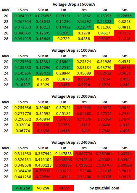
With contact resistance taken into account, it can be seen that it is difficult to meet requirements at high currents of 2A and 2.4A. As a result, cables only up to about 50cm can be used with 24AWG, or maybe even 1m with boosted source voltage. This is most significant for tablets.
For smartphones, with a requirement closer to 1A, 24AWG wires up to 2m could be sufficient, or 1m at 26AWG, and 50cm at 28AWG.
However, at 500mA (the original spec), it can be seen that it is possible to meet the stringent USB voltage requirement at every length with 20AWG wire, and 2m with 24AWG (probably by design).
The disadvantage of pushing more current at low voltages is very clear – the resistance causes power loss very quickly!
A corollary of this is that if you have a 3m cable, of 24AWG, then it’s likely your charge current is not going to exceed 1A (it’s probably 500mA-1A) purely because of the voltage drop that is caused by the cable.
Without Contact Resistance
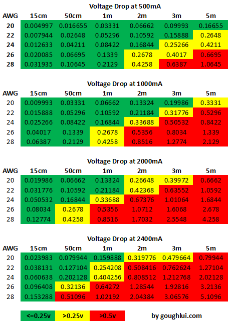
If we assume that connector resistance isn’t part of the equation, and look at the wires itself, the situation is a little less stringent, at high currents, but still illustrates the difficulty in keeping voltage drop under control.
One caveat of this, is that some vendors have realized the issue and decided to push the output voltage up to 5.1v or 5.2v, which is still within USB specification but allows for an extra 0.1-0.2v voltage drop. This is a potentially nice feature as it means the requirements on the cables are slightly relaxed (i.e. maybe even 0.7v voltage drop is tolerable).
It is also possible to see higher charge currents at the expense of voltage drop when the cell is fully discharged at 3v, as a ~3.2v input would be enough to start charging. Likewise, as the cell reaches full charge, the current tapers off, thus reducing the voltage drop. This might be happening already with some cables “pushing” what is possible. You know when it’s pushed too far when it doesn’t consistently charge fully (i.e. stuck at 94%, when eliminating all other issues).
Checking Your Cables
Depending on who makes your cables, it might be possible to determine what sort of wires your cable is made out of. Ever seen the text on the side of your cable? Well, here’s a quick primer on what to look for.
![]()

The two cables above are pretty much equivalent. The top cable says 28AWG/1PR AND 24AWG/2C, and the bottom cable says 28AWG/1P+24AWG/2C.
What this means is that the cable is made of one data pair of 28AWG thickness, and two conductors (that carry positive and negative) of 24AWG thickness. Remember, the larger the AWG number, the thinner the wire.
The data pair thickness really is unimportant when it comes to charging, so just look for the AWG attached to the conductors. The 24AWG thickness is pretty common stuff.

That being said, many of the cheaper cables utilize 28AWG/1P+28AWG/2C. This isn’t the best stuff for charging.

It’s possible to be surprised – I had to look hard to find this one which is 28AWG/1P 22AWG/2C. I’ve also seen 26AWG used, but 20AWG is almost impossible to find but is referenced by the USB standards.
Unfortunately, many newer cables are not marked at all as to their composition, and in the case of some cheaper cables, it can be suspicious as they often utilize non-type-approved cables of custom construction, or leverage “audio” grade cable without the appropriate twisting or shielding for USB operation. These cables still often work, but poorly in RF/EMI harsh environments, and often have thinner conductors, but this is not a given as many OEM cables are unmarked as well.
You cannot tell the thickness of the wire within just by measuring the external diameter of the cable either. In the case of the cables examined above, all three have extremely similar external outer diameters, but the wire thickness inside is obviously different. The printing itself could be faked as well, you never know.
Other problems can include low quality connectors which don’t fit well and exhibit high contact resistance because of poor quality plating.
Unfortunately, direct measurement of the resistance of the cable is complicated. This is because of the low resistance of the assembly itself – below 2 ohms – and resistance contributions of the connectors themselves which may make it less easy to quantify the cable resistance accurately.
An attempt can be made by making a custom rig with a USB A Female end and a compatible mating connector for the other end of the cable, and running a known current (say, 2A) through it to measure the voltage drop.
However, for most concerned users, an easier method can be to try measuring the charging rate of the device by noting the amount of charge accumulated from flat after an hour or hour and a half of charging. In the case of problematic cable, there will be a significant difference.
Conclusion
If you want to avoid any charging problems, it’s always easiest just to stick with the OEM charger and cable. Replacement of chargers with other models may result in incompatible signalling that can cause slow charging.
However, if you are going to replace your cable with an aftermarket cable, it would be best to see if you can find a cable with the thickest possible conductors for the power. If that isn’t possible, stick with short (to very short) lengths, as that always works.
It’s not possible to be sure of the thickness of the wire just by the external appearance – printings can be forged, insulation can be made thicker (quite common). Likewise, it’s not possible to easily directly measure the resistance by using a regular multimeter due to the complication of the connectors, and the very low resistances (sub 2 ohms) involved.
If you really need to have a longer cable, consider extending the primary side using a mains extension cable instead.
However, I think it’s clear that by pushing the current levels through USB to higher levels than originally intended, we are losing efficiency and reaching the limits of low-voltage power distribution. That’s why, the USB power delivery standard is opting for higher voltages.
Thank you for this. Very enlightening, as usual. I did check a couple USB extension cables of mine, and one of them, a 3m Belkin cable, is 20AWG. So, they do exist.
Thanks for the confirmation, very much appreciated! I’ve never seen one in the flesh, but now I suppose it can be clear why some cables are more expensive than others.
– Gough
Hi Gough,
I miss wire-to-connector resistance in your calculations (also 4x),
almost impossible to measure but certainly there is.
Thank you.
Miro
Dear Miro,
That’s definitely true, there’s almost certainly *some* resistance there, but given most cables are physically soldered, I would presume the resistance should be <1mohm, making it very insignificant compared to that of the connector contact resistance. For example, this experiment involving copper bars measured resistances in the *micro*ohms region (i.e. 1000 times less than a milli-ohm).
– Gough
Pingback: Review, Teardown: Two Popular USB Charger Doctor/Detector/Current Meters | Gough's Tech Zone
Very nice, complete and enlightening analysis of charging USB portable devices. You have saved me much digging into problems I have encounterd. Congratulations!
Hi,
One point i’ve found missing and i really want to know is the conductor itself! How it effect on charging if wires are of Silver vs Copper? Assuming the other parameters are same, like gauge & length of wire and voltage coming from the charger.
So which USB charging cables are better, Silver or Copper? I’ve experienced both but found silver more than copper.
Interesting question and one that deserves a reply comment – so here it goes:
Depending on how you’re looking at the cable, it can appear silver coloured for a few reasons. Maybe you’re looking at it at the plug end through clear moulded plugs – but it’s just solder that’s tinned the wires.
If not, and cutting open the insulation reveals silver coloured conductors, then it can be the case that they’re made from tinned copper conductors (which are easier to solder) but otherwise are substantially the same for conductivity as for copper. Otherwise, they could be cheap aluminium, which is a worse conductor (68% higher resistivity) and is more mechanically brittle.
It is unlikely that it is silver, with the exception of extremely expensive rip-off audiophile cables, due to the expense. But as a conductor, silver is only marginally better (5.4% lower) resistivity, so the result is mostly dominated by the connector resistance (in the case it is not ignored), or is so small as to be hardly notable.
– Gough
Great article. I am getting ready to purchase some USB cables for my phone and other electronic devices, and I noticed that they mentioned a number followed by AWG. Having no clue as to what that meant and how I should use that number to determine which is the better cable to purchase when comparing, I went in search of an explanation and found your site, which was very helpful.
I have a similar question about the silver vs copper, but mine is not about the wires inside the cable (as I think the only way to know would be to cut open the cable), but rather the connectors. It seems like those of copper are better, but how much better? How much of an impact do they have on better performance (charging sped or data transfer rate or other factors). Take for example this cable from Amazon, which has gold connectors [Link Removed] and states “Gold-plated connectors resist corrosion for signal purity” vs this one, which has silver plated connectors: [Link Removed] Both are priced the same, so I would assume in this case if I was looking to purchase that cable, I should go for the gold plated one? What if the gold plated one had cost more though? Would it be worth it to pay more for it, and if yes, up to how much more (i.e. 5, 10, 50% more) than the silver plated cable?
My other question is about extending cables. You state: “consider extending the primary side using a mains extension cable instead.” What do you mean by primary side? And by extension cable, I am assuming you mean any extension cable, such as this one: YCS Basics Black 3 Foot Cellphone / Tablet USB Micro Male to Female Sync & Charging Extension Cable: [Link Removed], which if yes, still leaves me confused about what you mean by primary side.
And finally, is it better to buy a longer cable instead of an extension cable, or does it not make a difference? For example, if I have a 3 ft cable, but I want a 6ft cable, should I buy a 3ft extension cable or purchase a 6ft cable instead?
Hope to hear your responses. Thanks
Dear Rob,
I have removed the links to the products from your comments as I do not wish to advocate such products to end users or give out links to just any products. I don’t tolerate guerllia marketing campaigns either.
However, the simple answers are that:
– Cables should be made of copper, as it has good ductility and low resistance.
– Connectors should not be made of copper alone as it wears quickly. Consider using a material to match on both sides of the connector – for USB this is gold plating as standard. Dissimilar metals may cause corrosion and oxidation to occur.
– Primary side means mains power. That means, use an ordinary mains power extension to bring the charger closer to you rather than keeping the charger at the wall and extending the USB side. This is because mains power is much higher voltage and the consumed current is lower and the extension leads are thicker, so it would not be affected as much by extending it from the wall.
– Using a longer cable is generally preferable to using an extension as it eliminates the resistance introduced by a pair of connectors, and reduces a reliability issue with the connectors. Loose-fitting USB extension cable connectors have caused issues with charging above 1A in my experiments, so a quality, thick (smaller AWG number) cable would be best, but not longer than absolutely needed.
– Gough
Thanks for the response. I wasn’t familiar with the term “mains power”, but from the explanation you gave I figured you were saying to use a power extension cord or power strip. I also looked up the term to be sure.
Hope this isn’t a duplicate..failed to login or so it appears so posting again
Fantastic post…a refreshing view. Read it yesterday and based on that posted on Stack Exchange as a tribute. Please delete if you think it is self publicity but it is not. It should help others was my intention. http://android.stackexchange.com/a/134970/131553
1. Charging current is 0.5 to 0.8C, so shouldn’t that be considered, say 0.8, instead of 1C
2. Still confused, when to use” without contact resistance” and when “with”‘? Could you kindly elaborate please?
A suggestion-please link the complete sheet to download so that odd battery ratings like 1.35 A can be read by people too lazy to calculate
Thanks a ton again
Charging current depends on the device and the charging scheme. The Lithium-Ion cells can actually accept a wide range of charge currents, and for larger cells, USB cannot really provide enough current to reach even 0.5C (example: a tablet with an 8000mAh battery – 0.5C means you need 4A charge current).
I did calculations with and without contact resistance just to illustrate how resistance can cause problems. You should always consider the with contact resistance values because that is what you would expect in practical usage. However, to work out the contribution from the wire only, then you can check the without contact resistance chart. Ultimately, a set of good connectors should have less than the contact resistance I used in the calculations, so practically speaking, you should observe a minimum loss of without contact resistance and at most (for a cable with connectors that are not worn out) of the value from the with-contact resistance.
As for odd ratings – I don’t really see much of a need to provide the actual sheet. If you want to be safe, choose the next value higher. If you just want a sense of the appropriate value, then choose the closest one (1A), preferring the green values. The main reason I say this is, again, each cable will be a little different because every connector, and every joint isn’t made the same and so calculating down to the millivolts for every current isn’t meaningful.
– Gough
Thank you very much-look forward to more of these useful posts. Subscribed:)
Sorry for multiple posts ,” For smartphones, with a requirement closer to 1A, 24AWG wires up to 2m could be sufficient, or 1m at 26AWG, and 50cm at 28AWG.” If from readings taken in yellow zone. So, I interpret it this way- for lower currents green/yellow zone is fine, for higher say 1.5 A add above, stick to “green zone”. Am I right?
That would be correct. While yellow-zone figures are not going to be strictly compliant with the USB -0.25v maximum drop, it may still be sufficient for a full charge as many devices can accept somewhat more loss of voltage without detriment to charging. With higher in-between currents, you need to be more conservative, so you should choose towards the green.
– Gough
Thank you so much for a prompt response
Thanks for the enlightening article! I’ve been looking for information on usb charging with real world tests like this for a long time! I want to make my own high current usb cables, for the data lines I can buy 26awg or 28awg wire for the same price per meter. Which should I go with? Is there any conceivable advantage to having slightly thicker data lines? When charging? When using for data transfer?
Also, what sort of flexible cable jacket would you recommend for DIY high current usb cables? I’m not able to mold my own cable jacket like manufacturers do.
Making your own cables is a particularly difficult endeavour with USB if you wish to have reliable USB 2.0 or above speeds on the data lines because the cable’s characteristics in terms of twists/meter, impedance and capacitance/meter, as well as screening/shielding need to be controlled to tight tolerances to ensure noise doesn’t get in and interfere with the data, and like-wise, the noisy sharp-edged digital signals don’t radiate interference that could compromise radio reception e.g. in the shortwave bands.
I would not recommend making your own cables from individual strands of wire, maybe except for charge-only cables, in which case you would also need to connect the device side D+ and D- wires in a way that the device would expect to indicate a high current charger was available (e.g. shorted for standard USB charger, or with resistors for Apple products). This does not apply for Qualcomm Fast Charge which needs D+ and D- to be continuous to “talk” with the charger. The other issue is getting and terminating quality plugs by hand which are not that readily available.
If you are buying “type approved” USB cable, which is pre-made and tested to USB specifications, then the cable should operate for data transfer just fine be it 26AWG or 28AWG on the data pairs. The 28AWG would likely lose more of the signal over long lengths (over 3m) whereas the 26AWG might have higher unit capacitance per meter making it more difficult to drive but will retain a stronger signal. As long as they are type-approved as marked on their jackets, they should be both equally good, but I might edge to the 26AWG solely because you’re getting more copper which might improve the strength of the cable slightly and make soldering slightly easier.
I don’t have any strong recommendations about terminating the ends of the cable, although you could experiment with commercially available silicone or hot glue and do a bit of an ugly “blob” just behind the connector on a “functional” standpoint. That being said, USB was not really designed for home-made hand manufacturing (although it is not impossible).
– Gough
Thanks Gough, I’ve cut several micro USB 2.0 cables and surprisingly, the data lines are often just run in parallel to each other through the cable’s jacket (many cables don’t have twisted data lines)…I wonder how important it is? Some cables don’t even use shielding inside the jacket. Do you think a “drain wire” is necessary for cable that is only used for occasional data transfer?
http://www.l-com.com/images/USB-tutorial_cable-construction.GIF
As far as termination, I was thinking of using some connectors such as this:
[Links Removed]
Thanks.
The drain wire is to be used to connect the shielding (braid/foil) to the connector shell to ensure it is grounded to ensure the shield actually works. Depending on your shield construction, pure foil on mylar is not able to be soldered, hence the need for a drain wire in contact with the foil on the full length. If shielded with braid, the braid can be collected together at one end and twisted together as a drain wire.
I have looked at the connectors and removed the links (as I try not to link to products I cannot endorse in some way). While I didn’t state it in the article, many times bad connectors are a weak link as well. Sometimes I’ve had to pinch the metal shells on the connectors to improve the clamping force to improve the contact to obtain full charging current. I suspect the “ordinary” connectors may not be ideal, but I have no recommendations either way.
– Gough
As for the twisting and shielding, as I mentioned here: http://goughlui.com/2013/02/02/some-cheap-cables-are-fine-some-are-rubbish/
Basically there are a lot of rubbish cables floating around. The effectiveness of a differential pair for transmission is highly affected by the twists in the cable as it permits for more “even” exposure to interference and provides a more balanced cable characteristic. The twisting is very important if you want the cable to work properly *as the standards intend*. However, since standards are always conservative, you will find that in less EMI harsh environments, with more accommodating controllers, and not caring for the interference you are probably radiating into the surrounding area, that such cables made from audio grade stuff will still work, or might occasionally connect at USB 1.1 rates with a “This device can perform faster” message.
For a similar reason, the shielding is also an additional line of defense and is part of the reason the pins sit inside a metal shell which should be connected to the shield.
– Gough
with so much advertising of which usb cable is best, i couldn’t figure out which one really is best and why. After reading this though, i definitely know what to look for now. also i wanted to point out that i did see a 20AWG cord but it simply charges only. for me personally i think it be better to get 2 separate ones, one for charging and one for data. Anyway, great article!
Hey, Thank you so much for this post. This is detailed and helps disassemble all the urban legend around the matter. I use an amazonbasics cable and find that it is satisfactory at dealing with upto 1.2As.
Thanks for this! I’ve recently started using a main power block with a 2m cable and USB sockets, and a cheap 2m micro USB cable, and was wondering which was to blame for my plugged-in tablet’s charge continuing to drop. And I thought I’d learned my lesson about buying cheap electrical accessories…
Thanks for your fabulous writeup on USB wire gauge. What do you and others think of USB cables that have no shielding? I bought a set from Tronsmart, and indeed they are 20 OWG for the red and black wires, as promised. But their website promises shielding, and in fact there is no shielding braid, foil or wires at all. Would be happy to upload a photo. I am an engineer so I have a pretty good idea, but in the real world, how common is no shielding? What do people think? How critical is the shielding in your opinion?
I’d have to say, from my own experience, no shielding is getting alarmingly common with some smaller thinner cables to improve flexibility and reduce cost, although such a configuration would never comply with USB standard requirements. High transition rate signals in USB will radiate interference and cause EMC/EMI problems without shielding, and the cables themselves become susceptible to picking up interference if the shielding is absent. (e.g. http://www.ti.com/sc/docs/apps/msp/intrface/usb/emitest.pdf)
Personally, while I find short lengths of unshielded cable to operate correctly in most environments, if you have heavy RF interferences (e.g. near a radio transmitter) or you have an unforgiving controller, you could end up with slower transfers due to data errors and retransmissions, or full-blown dropouts of connections during heavy use and occasional “this device has malfunctioned”/”unknown device” problems.
If you are using the cable for charging only, and will never use it for data transfer, this is absolutely not a problem as the shielding doesn’t really help with bulk DC power transfer. However, if you are using it to transact data, be aware that it may or may not work correctly in all instances.
– Gough
Great stuff, I wish there was more information like this around the Internet. Most what I see are misinformed opinions and commercial guerrilla marketing campaigns like you mentioned.
Great explanations here, thank you so much. I have a charging cable that i’m very happy with and to my surprise it’s a 28AWG/1P + 22AWG/2C.
Everything charges really fast.
Hi Dr. Gough, is this the reason why some original chargers use 5.3V instead 5V to compensate this voltage drop for their long cables ?
Dear Josep,
Indeed – that is the main reason for it. Generally, the USB spec demands that devices can tolerate 4.75 – 5.25V, so even a charger that is rated 5.2 or 5.25V is “within” spec. You can push this a little further – say 5.3V (or maybe it’s rounding error) since it’s fairly safe to say that at a 2A draw, there’s very little chance the cable won’t drop at *least* 50mV to bring it back within spec. The only danger is when charging has completed and there is virtually no draw – the voltage may be a little on the high side, but even 5.3V which is 50mV above the upper limit is unlikely to cause any damage (provided it doesn’t have added ripple spikes/transients).
Some chargers have even more sophisticated behaviour – for example, Anker’s power banks seem to have a current-dependent voltage compensation – the higher the current you draw, the higher the voltage at the source – a type of “slope” compensation to try and tune-out the resistive effects of a typical cable for better, more consistent charging.
– Gough
Thanks for the great explanations !
I just checked the MicroUSB power supply of my Raspberry Pi3 (the standard one), that is rated at 5.1V/2.5A, and it turned out that the cables indicate a 18AWG specification. That surely is something really qualitative, and my RasPi has never met any trouble with power.
But when I connect it to my phone (a Xiaomi Mi3, without compatibility for any Quick Charge X), it charges really slowly, it even loses charge when I use it while charging it with this… what makes me believe that the phone seems to draw a ridiculously small amount of current when it is connected to this massive power supply.
Do you believe that it is related to the fact that this power supply only has a pair of wires for the power and no data wire pair ? Is there any way to tell the phone to draw more current that he is willing to draw from it ?
The wire size of the supply sounds great, and the supply rating itself is enough, but that on its own does not mean that a connected device will charge quickly for several reasons.
The first, as you guessed, has to do with signalling. This lets the connected device know that it is connected to a dedicated charger, rather than a USB port or unspecified source of power. For most Android devices, shorting the D+ and D- pins on the connector will allow them to charge as quickly as possible as it signals the connection to a USB dedicated charger. It’s possible that the Raspberry Pi supply leaves these pins unconnected, as the Pi does not really care – but it equally could be shorted out inside the connector itself. The only way to know is to measure. However, there can be some complications with Qualcomm Quick Charge capable devices, as they do have their own sequence to negotiate charging voltage. The Mi3 does not appear to support QC 2.0/3.0 which charges at 9V/12V/20V, so I suppose this is moot.
The second is that the microUSB-B connector is really only “rated” for operation to about 1.8A. Most devices will only pull 1.7-1.8A anyway, which is enough for a phone, but if you were hoping to get a boost over the stock charger, it’s not likely because the phone is internally limiting the charge current.
If you want to know just how much current is going into your phone/battery, you can give the “Ampere” app a try. It doesn’t work on all devices, but where it does work, it will show you the current that is going into/out of the battery, noting that at different charge levels, the readings will vary somewhat, but it should give you an effective means of determining which chargers “match” your device the best.
For other devices with Quick Charge 2.0/3.0, because they charge quickly through raising the USB voltage from 5V to 9V/12V, they can deliver (within the same ~1.8A envelope) power around twice as fast. Unfortunately, a 5V-only USB supply could never match that, no matter how generously rated, due to the losses in the cables and connectors.
– Gough
If a tablet came with a 5.2v charger, is it safe to use a lower voltage charger (5V) with it?
This completely ignores Anker’s “over voltage” technology, or Qualcomms QuickCharge both designed to overcome resistance in extra long cables like 6 foot or 10 foot.
Please test again with materials made for flagship phones instead.
As someone who has no flagship phone, I’d be happy to if someone were to buy one for me.
But on a more serious note – Anker’s Voltage Boost effects were seen in the review of the Powercore+ 10050 Power Bank already (http://goughlui.com/2016/05/29/review-teardown-anker-powercore-10050-a1310-qc2-0-power-bank/) which was ultimately a voltage boost dependent on the current draw. The boost was **insufficient** to properly compensate for even 20cm of test lead, although it did do better than some unboosted banks (e.g. Xiaomi 10040mAh power bank had an output of about 4.88v at 2A, Anker had an output of about 4.93v at 2A or about a 0.05V boost) in a rather negligible way. So will it really help? Not by much I’d say. In fact, the bundled chargers that put out 5.2V or 5.25V at the top end of the USB allowed 5V range do a bigger help than the Anker technology does, although if your end device is a linear type charger, it would “waste” away the energy difference between the input and the internal cell voltage, thus resulting in increased heat and reduced charging efficiency. The physics is still the same – the voltage drop is still the same, with the exception that you now have a 200-250mV head-start.
As for QuickCharge – sure, running at 9V or 12V will see the voltage drop be a lower proportion (percentage wise) of the voltage, and thus, power can still be delivered a fair distance, however, the **physics** of the problem remain the same. The voltage losses stay the same for the same level of current. QuickCharge is predominantly used to deliver more power to the device for a faster charge, and **still operates at 1.5A** which is fairly close to the 2A used by many 5V only devices, and also close to the 1.8A that the microB connectors are certified for. Any loss of voltage and power will still remain on long leads – it is lost as heat, it’s just the user doesn’t notice it as much because the device still appears to charge at a decent rate rather than not at all.
Given the vastly improved cable choices that are available on the market since this article was published in 2014, and a much heightened awareness of the importance of thicker copper, shielded cables, and quality connectors, there is no excuse to buy the cheapest cables on the market and live with the suboptimal results regardless of which tier of phone or charging technology is involved.
– Gough
you are so right, I have these standard ebay type usb cables 1.5M, they look nice but charge my phone at 0.8A( I have a charge doctor connected to measure current) . I bought a 20awg cable and it will now charge at 1.2A, that’s 50% faster. I tried this on two different phone makes and its the same. I threw all the old usb cables out.
Hello Gouch,
Thanks for looking at this “issue” through scientific objectiviity…. and providing us real numbers, not just “science” from a products marketing information or online communities/forums towing the company lines.
I have several products from a well known “fruity” company. This company’s product lines always claim “only [fruity company] certified products” will work with each other.
Now lets say, they have 3 “certified” chargers, each with a different amp rating. They also have 3 “certified” cables of different lengths. And on top this this they have 3 different “certified” devices; one a phone, one a midsize tablet, one an oversized tablet.
Excluding losses at the connection points & variability in our imperfect electrical delivery system (basically voltage fluctuations at the outlet itself), the above permutations of charger, cable and device will result in different voltage drops at a very tiny specificity.
If it is claimed “certified devices” can tell “official” from “unofficial” cables & chargers (as the device itself holds coding for itself to identity specifics to itself), this woud mean under perfect conditions the device would only charge when the voltage drop matched a known set of values EXACTLY.
This would mean there is absolutely no tolerance whatsoever for “dirty” contacts, or conversely, a “certified” device would never charge given “perfect” contacts are impossible. But they do… so how is this?
In the industrial world I have seen microdot imprinting of serial numbers on large cables themselves to deter copper theft (ie those brilliant tweakers testing the Darwin theory at electrical substations), but this is a visual identifier only, not one that can somehow be measure or “read” by a connected device. Impurieties in the conductor’s metal itself would likewise cause voltage drops.
My guess is software coding to enact “planned obsolence” of devices (the most expensive piece in the puzzle) is at work, not some capacity to determine/measure the voltage drop across cables or charging devices. And knowing instruments to measure values like voltage at very high specificity are very expensive and are only as good as the contacts (and users themselves) I struggle to believe a mobile device contains such equipment.
Thoughts, and feel free to tear apart any parts of the above that I have missed or are inconsistent please.
I just happen to own multiple “fruity” products…. and at present (even with new charging ports) and new cables, can’t figure out why on a daily basis trying to get a connection (where charging occurs and stays occurring in an unchanged position) that works more often than not. 😐
I’m writing this reply remotely while I’m on holiday – it’s an interesting point you raise but one I think deserves a reply (even if it is abridged to some extent).
Fruity products in the early 30-pin dock connector days had no means to authenticate the cable. Instead, they looked for voltage combinations on the D+/D- lines which are the USB data lines that *do not carry charging current*. As they have virtually nil current, regardless of (most reasonable levels of) resistance, the voltage detected will be as “sent” from the charger. As a result, the fruity device can identify a “regular” 500mA USB port, or one of their own 5W/10W power adapters. Nothing too quirky about this.
Then, the fruit company decided that the 30-pin connector was too big, connected only one way, so they bought out the lightning connector system. In this iteration, the cable itself can be verified owing to the design – namely that there are more contacts than necessary, some of which are used to detect the cable itself. Within each cable is a small chip of their own design. It probably has some “secret” cryptographic function of some sort that the fruity device can issue a challenge to, and receive a response to check its legitimacy. Several “clone” chips had been made by other vendors, but none last too long as the operating system within the fruity device is updated to identify them. Initially, it was only a “warning”, but in later iterations, they just decided that any cable that failed the challenge would not be usable. As a result, only those cables from “certified” partners which are part of the “Made for i…” scheme that have paid their royalties can have their cables function and not be at risk of being blocked in future updates.
In other words, they did exactly what the printer cartridge guys did when they added chips to their cartridge – introduce a DRM system.
– Gough
Hi Gough and thanks for the response. Shortly after reading this, I did end up seeing the chip inside the lightning connector that had broken apart.
But I did make a recent discovery after countless hours attempting to get my phone to charge & stay charging over a year plus…. instead of pushign the lightning connector into the port by the housing around the chip/connections, I started pushing it in by the wire only. It wouldn’t seem the tolerances for making contact were so narrow, given the contacts on the lightning connector itself are a couple mm long each, but somehow the connector housing was pushing “forward” enough to keep the contacts from inserting far enough to actually make contact.
One would think the spring contacts in the lightning port itself would be designed to be under most circumstances in the middle of the lightning connector contacts…. but I guess not.
Hi Gough,
I have been searching the internet to educate myself and your site just simply did it with a breeze.
I recently asked a manufacturer for the specifications of the USB cable and this is what they said
20*0.15*2C+10*0.1*2C
This is for a USB to Type C cable. Can you explain how to decode this language and understand whether the cable is of good quality or not.
Hi Naquash,
This is common cable terminology when it comes to specifying the conductors themselves.
20*0.15*2C -> 20 strands of 0.15mm diameter by two conductors (likely the power carrying pair)
10*0.1*2C -> 10 strands of 0.1mm diameter by two conductors (likely the data carrying pair).
Of course, you will need to use some basic math to convert this into mm^2 area – for the power pair, this would be:
20*(0.15/2)^2*pi = 0.353429…mm^2 cross sectional area.
You can then use a look-up table to convert it into AWG (American Wire Gauge), such as https://en.wikipedia.org/wiki/American_wire_gauge#Tables_of_AWG_wire_sizes – this tells you it’s about an 22AWG wire (a little above 22AWG, but not quite enough for 21AWG).
Hope this helps.
– Gough
This is a very good write up based on theoretical calculations. What about real world results? Could you have not set up a test rig to compare theoretical to actual results. For example, the resistivity figures from wikipedia are temperature dependent and during charging the cable temperature increases. Its a very important factor neglected in the above write up and I would like point out that this temperature dependence is factored in household wiring and wires are rated, for example at 90 deg C because the temperature does matter.
The real world results are even more of a mixed bag. If you haven’t already seen my other article about contact resistance (http://goughlui.com/2017/11/20/usb-connector-resistance-another-reason-for-slow-phone-tablet-charging/), there is also signalling compatibility and battery internal resistance/charger IC thermal considerations. I’d like to see you set up a test rig (if you think it to be easy) given the low resistances involved and the fact that each plug and unplug could change the results dramatically. I’ve personally tried even plotting charging of power banks to find the results differ significantly on plug-unplug – the truth is, however, a thin cable will always make things even worse.
Heat-related resistivity changes are minor by comparison. No charging cable should operate at any elevated temperature – the reason is simple, if it heated significantly, the energy was lost in the cable and not sent to the phone or tablet device. This of course, is not such a big issue for mains house wiring as the mains is capable of sourcing a very very high current, although the temperature dependence is more important for “fault condition” cable protection as plastic insulation is rated to a certain temperature for its rated lifetime. It’s not intended to operate at such high temperatures in general.
Lets take a hypothetical cable that “barely” meets USB specification (0.25V drop) at the maximum realistic current used today (2A). That is a power dissipated in the cable of 0.5W. If this was concentrated at a small point, that could heat up and cause melted connectors and potential fire. But in a properly operating cable, the dissipation is spread across the cable. Depending on the air circulation in the room and the insulation, the heat is carried away at varying rates making an accurate analysis difficult.
However, using PCB design rules of thumb, it seems that 2.2A can run through a 100mil (2.54mm) trace on a 0.5oz copper board (17.5um thick) for a 10 degrees C rise (based on figures from eevblog’s uruler3). This equates to an effective copper area of 0.04445mm^2, or 31AWG – i.e. thinner than the worst wire normally used. The temperature coefficient of copper is +0.393%/C, so assuming a 10 degrees C rise, that will result in 3.93% increase in resistance. But most cables will be thicker, thus the temperature rise is smaller than this, thus this is a worst case scenario as far as I can see.
Using the 1oz Masked Copper data (35um), it seems that 100 mil (2.54mm) track can carry 2.42A for a 5 degree C rise, which matches closely with 28AWG at ~0.08mm^2. A 5 degree rise is only going to result in 1.965% increase in resistance for the realistic worst case cable under the highest realistic current. You could argue that the insulation around the wire is thicker than solder mask, but I think this is moot. Such an increase in resistance is equivalent to making a 1m cable an extra 2cm longer …
Worse still … you can get this level of temperature change just by stepping in and out of an air-conditioned room, or day-night cycles. This is why I wouldn’t really worry about it so much.
– Gough
Thanks for the article, very enlightening. I would like to share my experience if you don’t mind. I had similar problems trying to replace a cable for a tablet charger (Asus MemoPad) with all those negative effects including discharging. So I decides to use a cheap eletronic wattmeter (<$10) as a measuring device. The charger was 5.5V/1.35A. The cheap non-functional cable showed 1.7W while connected, torn but still working oem 3-4W, and recently purchased promising one 6-7W. Btw, I recommend also having a wattmeter since it also reveals many shiny facts about electricity consumption in household.
I ran into this when trying to work out why an old Nokia phone was struggling to charge off a USB charger with an adapter cable. I initially suspected the charger, but plugging a USB power meter into it showed it quite happily delivering 5.1V/450mA. The cable, on the other hand… I don’t know what it was made out of but there was only 4.1V coming out the end of it and the phone did not like that (the current/voltage was bouncing up and down as the phone attempted to charge from it).
Curiously enough a Nintendo 3DS was perfectly happy to charge from that same cable/charger combination, despite claiming to need 5.2V.
Personally, my USB connectivity-related problems boil down mainly to the fact that, over a far too short period of time, the connectors appear to oxidize (or, in any case, degrade), which leads to increasingly frequent disconnects and USB-related system time-outs/freezes.
I use the shortest usb cables that are still practical, to minimize the problem you discuss in your article, due to the reality that cable length is not only the primary determinant of voltage drop (indeed why power lines conduct alternating power, since in their case (long) distance is the independent/constant factor), but also that length is far more readily discernable (indeed, it’s usually prominently displayed as part of the product description) than wire composition. Even your tables indicate that a 15cm (6″) cable works in every circumstance, irrespective of any other factors involved. Nokia used to supply such USB cables with their devices in the past — I have one and it continues to function perfectly, after over 10+ years of use. In the 90s (and before), in the days when high density SCSI was still popular, cable length was the only determinant when it came to guaranteed communication bandwidth. At that time, 6-12″ cables were fairly common.
But like I said, that isn’t the primary issue — at least not in my case. In fact, I found this blog entry while frustratedly seeking information that might vindicate my views regarding the dismal quality of the singularly most important determinant when it comes to USB reliability, without whose continued, consistent functioning none of the iother factors matter. And that happens to be the point of contact between the components, which is the connector itself. I have cables that held up well after years of frequent use. But I have many more cables that started to degrade quickly and became effectively unusable within less than a year.
To be honest, connector issues are not that common and they shouldn’t be especially where you use branded connectors. This article deals with resistance of the cables alone, hence the title “USB cable resistance”. However, that being said, I DID write about connector resistance and profiles here:
http://goughlui.com/2017/11/20/usb-connector-resistance-another-reason-for-slow-phone-tablet-charging/
As the issue is rarer, nobody seems to read that article …
That being said, I suspect it’s all because of another cost-saving measure in China, as I mentioned in that article, where the gold plating is not gold plating at all – some may look gold coloured but wears off/oxidises.
– Gough