

When I get a little time, I like to go through the “donation” pile and do some testing. As it turns out, I was gifted a set of four Cooler Master Xcraft External Hard Drive Enclosures along with matching power supplies and cables. These enclosures are good for 3.5″ IDE drives, and seeing as IDE ports won’t be any easier to come across in the future, are useful if just to have another method of accessing IDE devices.
Of course, in the case of hard drives, using an IDE to SATA adapter and a modern bridge or SATA port is theoretically possible, although in my experience, such methods are a little finnicky for a few reasons – one of which is the need to match power plugs for the drive and adapter, and another to ensure the polarity of the plugs are correct. Even then, you might encounter strange timing bugs which means that it just won’t detect. That method certainly does not work for ATAPI devices such as optical drives.
Of course, if you still have a computer with a PCI slot, an IDE controller card is still an option, and older machines with physical motherboard-integrated IDE ports an even better option.
Unfortunately, it turned out these units were troublesome. A drive could be fitted, but nothing happened. The problem? A classic. Bad power supplies.
The Patients
Of course, with four enclosures, there were four power supplies. Testing the power supplies with the Tektronix PA1000 showed a healthy, if slightly thirsty, draw of about 1-2W at idle on three of the four supplies. The final supply had absolutely zero draw from the mains, so it’s probably a little more further-gone than the others.
Plugging the three supplies which worked into enclosures with drives and powering them on resulted in the front light coming on red, but otherwise no other action. No spin-up, no detection. However, close observation of the power supply showed a slight periodic dipping of the green power LED and a very quiet chirp/squeak. This is a good sign that the power supply is “collapsing under load” and restarting. Chief culprit? Bad capacitors. Again. You know how much I enjoy these …
Power Supply 1 and 2 in the Operating Theatre
I faced my first hurdle as soon as I decided to try repairing the units – there were no screws and no obvious way in. The case would have to be cracked open. Using a technique I had previously used, I shoved a flat-blade screwdriver in one side of the moulded rubber strain relief of the cable, and gave it a good prying until the seam started to crack in stages. Before long, two supplies had opened up, although a split did develop in one of the cases.

The power supply itself is marked SK Power Supply, model SKA-0512-20B. For convenience, the pin-out is listed on the rear – which is very helpful in case you want to splice in a different one for a replacement or just check compatibility. Other vendors used similar connectors with different allocations (e.g. Lacie) and damage is a high possibility where the pins are exchanged.

The power supply, as opened up. This was the first unit that was completely dead, and while it had no odour, the primary side capacitor was slightly bloated suggesting it may have failed. The second unit was one that couldn’t hold-up the load, and again, was clean inside but with no obvious capacitor failures. The transformer is labelled SKY, and the brand of the power supply is SK – these both refer to Skycable – the company that produced the power supply and the enclosure on behalf of Cooler Master.


Views from the side show copious use of insulation tape, and show the trauma on the primary side capacitor a little more clearly. The supply has a lot of adhesive goop over components as a form of vibration-support, but it has gone brittle and brown over the years.


A look at either end shows that there is a primary side fuse near the input socket, wrapped in heatshrink. On the unit reporting a zero load, the fuse had opened. The secondary side shows a cluster of capacitors.
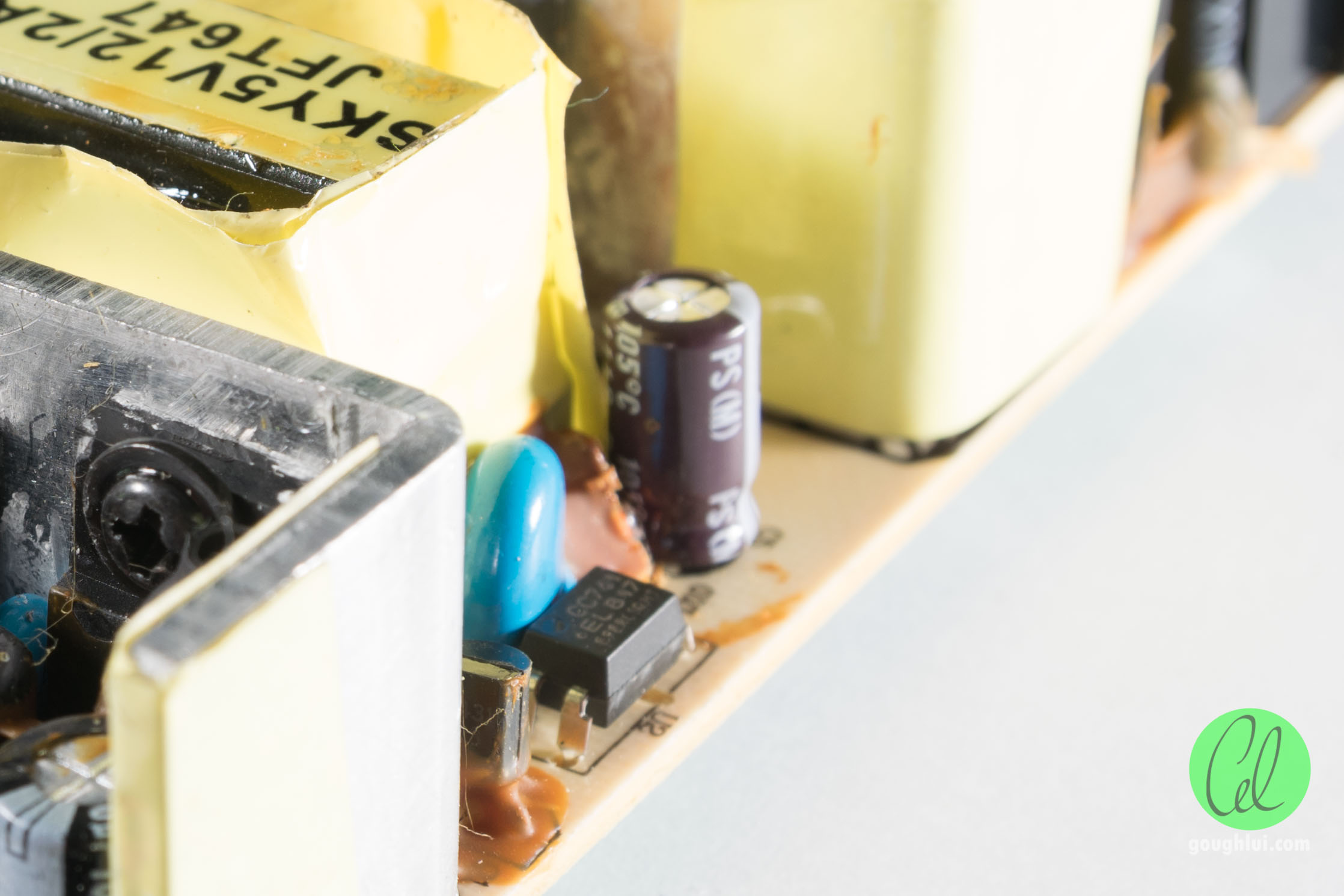
This is where something odd was observed. While it’s not unusual to see Chinese capacitors in devices, often I see the brand in question spelled ChongX. In the case of this unit, it was ChengX and Cheng (primary side capacitor). So in other words, they used a counterfeit copy of a questionable quality Chinese capacitor. That can’t be good. Apparently, they also come spelled as ChangX.

The underside is covered with a single sided PCB with three holes (two used) as a shield. A pretty interesting way of making a shield, I thought.
Taking an inventory of parts, I needed:
T2A PCB Fuse
Heatshrink
47uF 400V Capacitor
47uF 35V Capacitor
2x 1000uF 10V Capacitors
2x 1000uF 16V Capacitors
Rummaging through my parts box and after a quick order through element14, I had the necessary parts. Of note is that they could have used just all 16V rated 1000uF capacitors, but I think they decided to use the other rating to save money. Because I did have the voltage rating as per the original, I decided to use it anyway.

The surgery begins on the completely dead unit. The shield is to be desoldered. In the past, I used copious amounts of solder (to dilute the mess that is the lead-free solder) and quality desoldering braid (Goot or Chemtools branded stuff). Now, I’ve taken a liking to using a good desoldering bulb. While I’ve never had much luck with the solder-sucker spring-loaded pens, the desoldering bulb seems to do a great job, even if it is a Jaycar product. Much cheaper than wasting a mile of braid.

I thought the dead unit may have just had the primary capacitor short out internally, resulting in the fuse blowing and a simple fix … I was wrong.

The sooty black mess shows that at least three of the SMD resistors had smoked quite nicely. Despite knowing the values owing to having a number of other units, I felt it wasn’t worth pursuing repair any further since the carbon deposits and high heat may cause safety issues in the future, and its proximity to the controller IC makes it impossible to rule out collateral damage. It wasn’t critical to have repaired this unit, so I gutted a few parts from it, and moved on to the second unit.


The first thing out was the primary side capacitor. It was secured by glue that easily crumbled as an attempt was made to remove it. With the desoldering bulb, and some patience, the pads were cleaned nicely without using any braid.


 The replacement fit just fine on a diametric basis, and was soldered in with nice shiny joints thanks to the leaded solder. Unfortunately, it was about 3mm taller than the former capacitor – I thought that would be fine since they should be given a little room to vent, right?
I moved onto the 47uF capacitor on the side, which was also fairly easy as it came out without any protest. Again, the desoldering bulb fared just fine – heat up each pad alternately while rocking out the old capacitor, clean it out with the bulb, put a new capacitor in following orientation, solder and clip the leads.
The challenge was the crammed secondary side capacitors – the adhesive was still holding strong, and the capacitors were right up against each other, so rocking was not a possibility!

As a result, I resorted to my brute force technique. I think it’s pretty obvious what I did – grab a set of pliers, yank the capacitors off the board by force, then suck off the solder from each pad thus allowing the remaining leads and electrode fragments to fall out.


That was, very successful, despite the crudeness of the technique. The downside was that the capacitors were not saved for analysis (if that was desired). Given the awkward solder pattern and proximity of the joints, it would have taken ages to try and get it out any other way. On the plus side – still didn’t have to use any braid.

Unfortunately, this is where I get bitten in the arse by the fact that the original capacitors were of a smaller diameter than the replacements. It happens occasionally – the original capacitors may indeed be in such a small diameter that quality replacements of the same size just aren’t common or available. As a result, I tried to do my best by cutting down the LED and moving it down to the board, and squeezing it into the side. It is about 2-3mm proud of the heatsink. I thought that would be good enough.
I did have a thought as to whether it would be possible to omit capacitors, or substitute smaller values, and it seems this board uses a C-L-C pi filter to filter ripple, hence the two capacitors per rail. As a result, omitting capacitors would compromise the filtering, and changing the values may alter its effectiveness (although probably not as badly as failed capacitors would). So, it seems you can’t use a 2200uF capacitor in substitution, although maybe substituting 820uF in both positions may be sufficient at the cost of slightly increased ripple on the output.

A neat job overall underneath. The lack of braid usage also means a lack of braid flux residue – no black marks for once! The shield was soldered back, and then … I tried to reassemble the unit.
The Aftermath

Rather embarrassingly, despite the hack to the LED, it turns out that the wedged capacitors on the secondary and the replacement primary side capacitor were just 3mm too tall and thus, the case could not be closed. The next best thing was to wrap the whole unit in tape – it’s “safe enough” for my own personal use … maybe I can even say the ventilation has been improved … *chuckle*

On testing the unit, it came up just as expected, and the drive spun up just fine. All was good again.

I even discovered an old IDE drive in my room that was part of my old FreeNAS installation, formatted in UFS2, that I managed to recover the data from via Ubuntu (running live, inside a VM). Note that the auto-mounter is not capable of handling the drive, so make a mount-point manually, and specify -t ufs -o ufstype=ufs2 when mounting. Support in Ubuntu is read-only, but that’s really all I needed.
Conclusion
It’s interesting to see that the fallout from bad capacitor electrolytes and just plain poor counterfeit components is still continuing on. While it is frustrating, at least where it is the only fault, it can make for a fairly simple repair. Leave it too late and the collateral damage may make repair a little complicated, and uncertain. In this case, I didn’t even attempt to resurrect the blown unit.
Unfortunately, while most repairs are mostly uncomplicated, close narrow spacing of components and Z-height restrictions can be a killer as in this case, as some of the cheap capacitors were providing high capacitance figures in small volumes unmatched by common high-quality capacitors from Japan. Getting things desoldered can be a challenge as well, as some aged lead-free solder is hardly co-operative. While the one repaired was not aesthetically saved, at least it is functionally repaired. Further challenges can be had in just getting the case open without destroying it entirely – the days of “screw-based” enclosures seems limited, thus repair will become more of a challenge.
The fate of the remaining two power supplies remains to be determined, but may be also repaired in much the same way should the need arise. However, I’ve grown to be fond of my desoldering bulb, which should save my desoldering braid to when it’s really needed.
I have a Cooler Polar 3.5″ HDD IDE External USB (wow, lol) that i’m having a hard time finding what power supply voltage etc i would need…it has nothing on it (that i can tell at least) to let me know either, so i was hoping that with all your knowledge you might be able to tell me…i think it was either 9 or 12v…i actually made a 12v for my other old external enclosure, an iomega MDHD500, and it actually works, lol…so before i destroy anything by using that i thought i’d seek some advice, haha… thank you for posting pics and info on wiring/soldering…
Also, I apologize if my question isn’t in the correct location and i wanted to add (after re-reading what i wrote) that i did search the net a bit and found similar items, but not this one exactly and i was worried about getting the polarity wrong since i didn’t see any markings—or my ignorance of electronics (not for lack of want of the knowledge, lol) is probably not helping if the info is actually somewhere not so easily seen. i know just enough about electronics to be dangerous, lol, but i do take that into account, and i continue to try to learn as much as possible with soldering and electronics- i’m always curious what’s inside of everything and it’s also very satisfying to build and repair things!! thanks in advance, sorry TLDR…
I have no idea as to which unit you have, but the rules of thumb for 3.5″ non-bus powered external enclosures are as follows:
– If it has a DIN style round plug with many pins inside, the pin voltages and allocation are not fixed. Ones with six pins tend to use adjacent pairs of pins to carry 5v, 12v and ground. Many choose to have the bottom pair of pins be ground (when the plastic tongue is face up), but which side is 12v and 5v is not certain. If it has four pins, normally one pair is +12v and ground, and another pair is +5v and ground.
– If it uses a single round barrel jack plug (e.g. a 2.1mm or 2.5mm centre pin + 5.5mm outer diameter), then most drives use a 12v 2A adapter with centre positive polarity. This is because the internal drive requires 12v and 5v, and internally, the bridge board has a 12v to 5v DC switching buck converter to provide the other voltage rail. This is a quasi-standard that most Seagate/Western Digital external drives adhere to as well, although multi-bay units will use proportionally more beefy power supplies.
If you want to be as safe as possible, I’ll advise you disassemble the unit and check inside. Try tracing the traces on the PCB from the back of the power jack or running continuity tests to the 12v (yellow) and ground (black) connections on the drive power connector as a double confirmation. However, 9v would be very unlikely at least for a 3.5″ drive based external drive, as the spindle motor requires 12v to operate.
Best of luck, but as usual, you take ultimate responsibility for what you try. I cannot be held responsible as this advice is given in good faith.
– Gough
Thanks for getting back to me so soon…the good news is i haven’t started any fires yet, lol…oh and unless you have unusually long arms, i wouldn’t hold you responsible for any advice you give; but i get the preface–and i’m sure you’ve dealt with, i’ll just call them “difficult” and certainly unappreciative people! so i have the thing open and i inspected the tiny board and didn’t notice a 12 or a 9 anywhere–so i focused on the back of the power switch: 6A 250V AC, 10A 125V AC
Also next to the power switch is HD-D16-U2…(I did of course look that up with no concrete results, only similar items)…The power jack is round so i think i’ll go with your deduction of 12v and try the one i made… ? that one does work with the other iomega enclosure but it gets a little warm…not hot, just warm…? the ide cable came apart when i took the drive off so i’ve gotta either put that one back together (maybe not) or prob better option a different ide cable…basically, i broke it, lol…also something smells slightly burnt so it may not work if it smells like that right?
If there’s no appropriate marking on the board, that’s a bit unfortunate. The markings on the switch are just “standard” – a lot of generic switches have much the same ratings and it doesn’t tell you concretely what the power input should be (except for “stay below these limits” or risk the switch failing).
I’d say a regulated 12V 2A power adapter with a centre positive polarity might be the best bet. Ideally things shouldn’t smell burnt – a light burn smell might just be because of age and being stuck in an enclosure. A strong burning smell may indicate the wrong polarity or voltage had been previously applied and causing either some chips to become short circuited or damaging a TVSS protection diode on the drive itself. Smoke after a few seconds is a sure indicator.
If you’ve already got it open and you really want the data … you can’t go wrong with just taking the drive out and plugging it internally into an old machine that has an IDE port?
– Gough
oh no, i’m just doing this for fun…a friend brought over 5 older ide hard drives and i don’t want to hotplug them so i figured i’d try my old external enclosures…haven’t had them out in a long time but i do remember them both working, lol…havent seen any smoke yet…
i did notice the cheng capacitors, too…haha, see i’m learning… 🙂
i’ve gotta dig up an ide from the depths of the earth…i’ll literally, keep you posted…lol
oh,before you run for the hills cuz i’m bombarding you, lol, i really need to ask a more important safety question about a different pcb board–this thing has been sitting in my living room FOREVER –it’s a Samsung LN32A330J1DXZA flat screen tv–don’t know the history of it as my neighbor gave it to me since she knows i like to fix stuff, but she had no history on it either–and what little i do know about tvs insides, is that it is somewhat ‘dangerous’ if you don’t know that the electricity is still running thru it, even off…so i was super careful and waited a few days after doing a plug in test before opening it up…so i opened it up and unplugged the flat cables and other wires so i could check out the board—any of the info i’ve read has said that most of the time all that needs to be repaired is a blown capacitor in these tvs that are now using cheapass capacitors that allow the tvs life to be about 6 months if that..and in this case i did see a blown capacitor on the board– 10V 2200 microfarad—my questions are so many, lol, but i was wanting to know the exact areas that i need to be aware of safety-wise on the tv after i solder a new capacitor (or get a new board for the tv even)…i have a great soldering iron and i practice alot but i still suck at it…it is soo hard to get anything to stick-and i’m using the correct ‘tin the tip’ and all methods with flux and all…can’t figure what i’m doin wrong…whole other show, right? LOL…ok, so, my other question is about microfarads–is it safe to put a capacitor in that’s over the needed amount? e.g. if the needed cap is 2200, but i have a 3400 instead, is it ok/safe to use?
Generally speaking, most electronics are safe to work on if unplugged and the capacitances inside are discharged. In the case of your TV, being an LCD unit, it shouldn’t have the high voltages you might expect of CRT or Plasma TVs and is comparatively safer to work on.
Replacing capacitors with higher microfarad ratings is probably not the best idea. It probably will work if you don’t go too overboard (most electrolytics are 20% tolerance anyway) as many of them are just used for power filtering purposes. If you do go overboard, the high capacitance may cause power converters to fail to start up due to protection, or the peak inrush current is so high as to damage the MOSFETs of the power converters. However, if it’s used in a timing or signal bypass role, changing the capacitance will have adverse effects on the circuitry. Best to match the capacitance and working voltage ratings if possible, although substituting a higher voltage rating is acceptable although often it won’t physically fit.
– Gough
ok thank you…i may just get a new board if i can find one cheap enough–too bad it won’t be as cheap as a capacitor, lol…so the external encl. has power now and nothing is warm yet, but it’s also not registering on windows…but that could just be the drive so i’ll try another drive….the p.s. i made is 12V 1000mA so i’m hoping that’s enough power, but since it’s not registering…?
Check to see it’s spinning happily, make sure all your cables are well connected. Try a different cable. Check inside Disk Management or Device Manager in case the disk is unformatted or blanked or non-Windows (e.g. Mac or Linux formatted). I’m not sure 1000mA is quite enough for many hard drives, it’s a little borderline.
But that being said … I think you should take some troubleshooting into your own hands :).
– Gough
well, that wasn’t good…it froze my computer up so i had to restart…thank you so much for all your help! it is truly appreciated! 🙂
Do you think a LaCie 4 pins PSU with the +12V and the +5V pins inverted could fit (the one I ordered delivers 2A by the way) for such external HDD enclosures ? Thank you for sharing your insight.
I don’t have any LaCie equipment on hand, but I have helped others and it seems they use a similar plug. I can’t say for sure whether it will fit or not, but the LaCie pin-out is definitely not compatible with the Cooler Master pin-out which resulted in my friend frying a unit in the past. The only time I’ve met the LaCie power supplies are when they have failed, but I tend to repair the supplies (some of them are simple re-cap jobs) to get them going again and similarly this holds true with the supply that came with the Cooler Master Xcraft enclosure.
Failing all else, you could extract the hard drive and plug it internally into a compatible desktop machine.
– Gough