


Another day, another salvage – this time, a Dranetz Series 606-3 Line Disturbance Analyzer. Just a forewarning – this post is image-heavy! Anyway, this is another one of those items being thrown out by UNSW Electrical Engineering, who can resist the shiny chrome metal latches, baby blue painted metal (the beige of 40 years back) and integrated carrying handle? Not me. Not even if it weighs about 8kg and makes my arm sore just to carry. I bought this home as another bit of interesting gear to have …

That’s the top with integrated carry handle. They just don’t build things like this anymore. The label at the top is for Electrical Equipment Ltd. Industrial Division 192 Princes Highway, Arncliffe, N.S.W. which is now the home of Plastix and IDS. Oh how things change. The bottom label is more surprising though –

So many questions – Sydney County Council? Measurements Laboratories? Affiliation with UNSW?! I have no idea what this is all about, but it’s definitely interesting.
The device itself, as you could guess from the name of line disturbance analyzer, is a piece of test equipment that is used to monitor the AC power quality and record disturbance data. This can be important where there are interruptions, impulses, sags, surges, swells and other power quality issues which can affect sensitive equipment. Looking around, there seems to be one source of a manual online, but it is a bit of a brief “quick-start” like guide. The company itself is still alive, although they don’t offer any support documentation for this device.
Popping open the lid, on the inside, we can see the wiring diagram for different single and three-phase connections. There’s also a spare key for the key-switch lovingly taped to the inside of the lid. Sorry for the shaky picture.

The actual front panel looks like this:

Sorry for the shaky picture, but the centre houses a thermal printer and a roll of paper, with the blue lid hinging downward to open the housing. There are twist-switches to adjust nominal voltages, and trip/alarm thresholds across the top. On the left and right of the printer, there are push buttons for controlling the clock speed, feeding paper, printing a test summary, turning alarm and printing on and off and resetting the device. Finally, the bottom left has a key switch to change between off, operate, and set modes with an LED below indicating the power condition – on, or on battery.

There’s the front lid hinged open, showing a full-roll of thermal print paper already loaded.

The bottom of the device shows a flex cable attached to the measurement terminals. The cable has enough conductors for a three-phase measurement, but the connector on the end is for a standard 10A GPO, single phase. The unit has Option 102 fitted so it can operate in 220V countries (such as ours) – which accepts an IEC power cable input on the left side.

That’s the other end of the flex lead, with the other phase cores folded back and taped to the cable. Not a very pretty sight. Removing the guards from Option 102 and the measurement terminals …
It might not be clear, but already staring at this, I can already see this device is pretty much a lost cause. [Exercise: Find the trauma!]
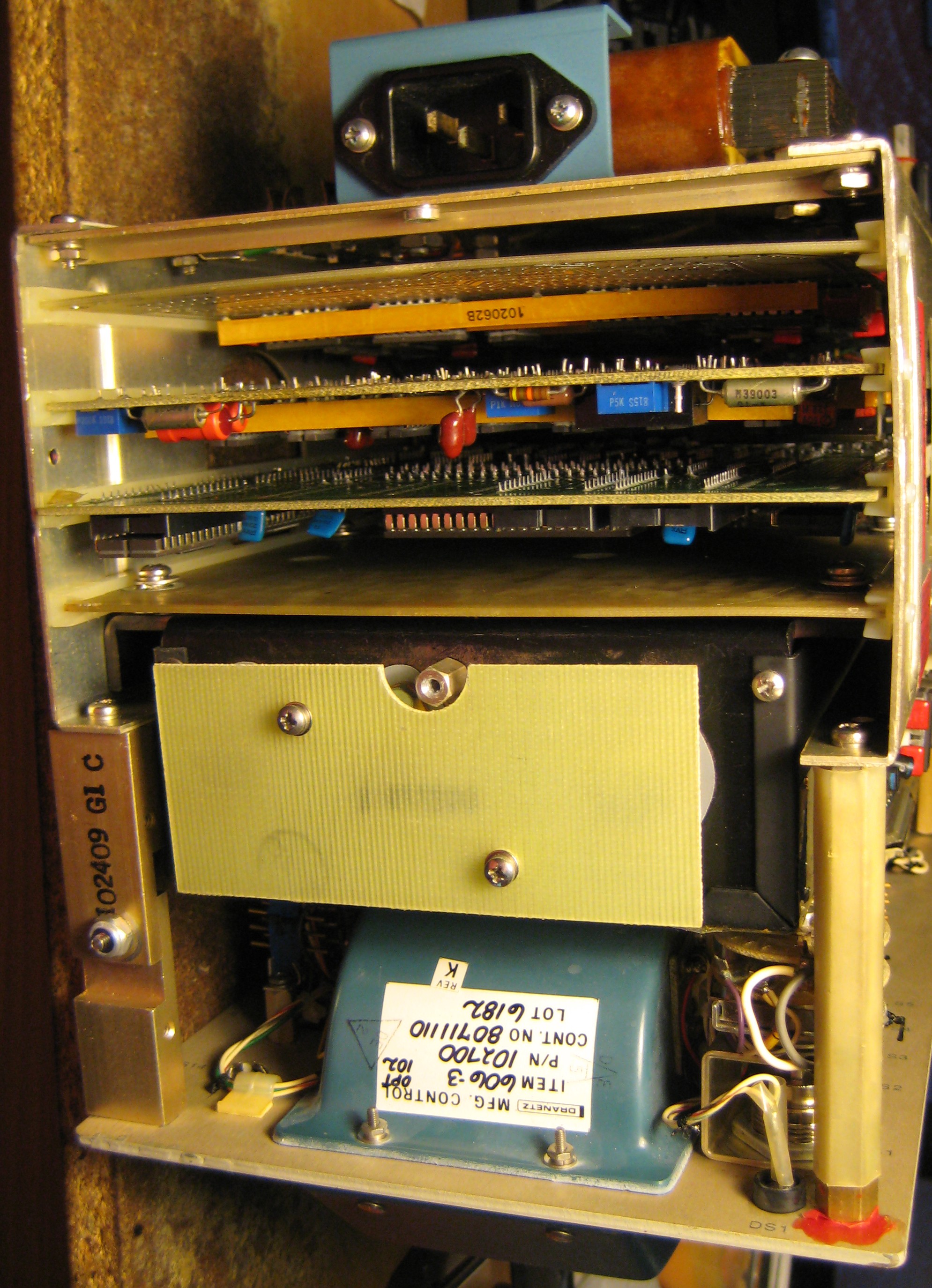
We can see on the transformer, the date code implies it was manufactured Week 20 in 1978 which is 35 years ago. The transformer looks quite traumatized – that’s a nice burn mark.

The second clue is that one of the primary fuses are quite catastrophically blown …

A usual sighting is the tarnishing of terminals and other metal surfaces – this dark oxide buildup is common, that’s why I reseat and clean most things when checking them out.

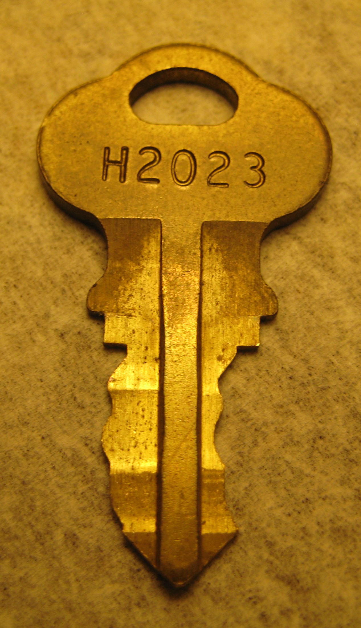
Lets just pause for a sec and check out the keys – it’s a quite unique and old-school design:

Taking apart the six screws with locking washers – four on the bottom, two on the side, the compact chassis slides out.


Side view of the chassis – you can see on the first image that there’s a swelled up corroded Ni-CD backup battery pack. The card cage is in the rear half of the device. On the second image, you can see the front panel board and buzzer.

The top view reveals more interesting stuff. The backplane of this device is completely made by a wiring harness with crimp-style slide-on connectors! Not wire-wrap as one might expect of this type, but not soldered or PCB/PWB’d either, so it could be reconfigured and repaired. The underside is shown in the second image, with the card-retaining brace removed – so you can see there are four modular boards which can be removed – everything is built to be repaired.
So the first thing I did, because I decided that this was already a lost cause and is due to be disposed, is to take everything apart without regard for putting it back together. This means a ruthless teardown – so we’ll get to see every corner. The first thing I did was remove the thermal printer on the front to find a nice surprise –

The rear PCB on the printer has many chips – almost everything is socketed, almost everything in ceramic packages! One of them appears to be an Intel CPU (the big one near the bottom). No solder resist or silk-screening on the PCB …
Taking a look at the paper input, it’s interesting to note that they used optical detection to detect low-paper condition.

Now back to the modular boards – which took a lot of wiggling to get out. It was a big struggle. The first board is the CPU board –

It’s probably the most modern board of them all. Green solder resist, with Intel CPUs, Intel ROMs socketed. This is probably the board with the least sockets too.

The rear of the board shows the classic copper-bubbling as if it’s delaminating partially from the board. This seems to be a normal symptom of boards this age. Next are the two Analog boards which have no such fancy solder resist – just tinned finish. Lots of sockets!


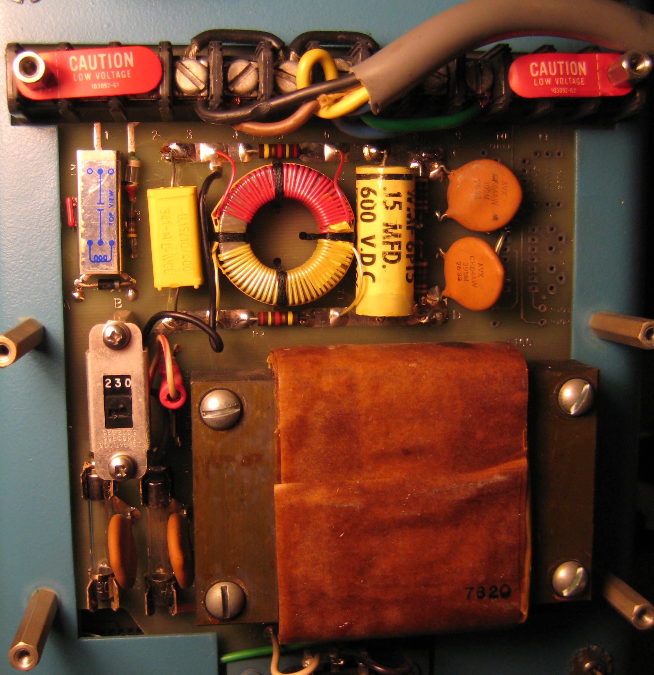
Finally, there’s the very unusual logic-and-power board with a large power supply hanging off the board. This board is traumatized too …


You can also see some old diodes which look like a thick ring with wires coming out of them! The heavy power-supply unit which is socketed and screwed to the PCB – that’s the next thing to get cracked open –


We can see that they probably expected this unit to fail – so they made it modular and replaceable separately of the logic that is housed on the same board. This, along with several boards are corroded by the outgassing from the Ni-CD battery pack. Nasty stuff – that’s why batteries need to be taken care of, and not kept on float forever.
Taking off the lid, we see a very compact inside … with an edge connector and all …

Definitely traumatized. The brown marks on the rear of the PCB give it away. It’s also visible on the outside of the large cap they shoehorned inside.

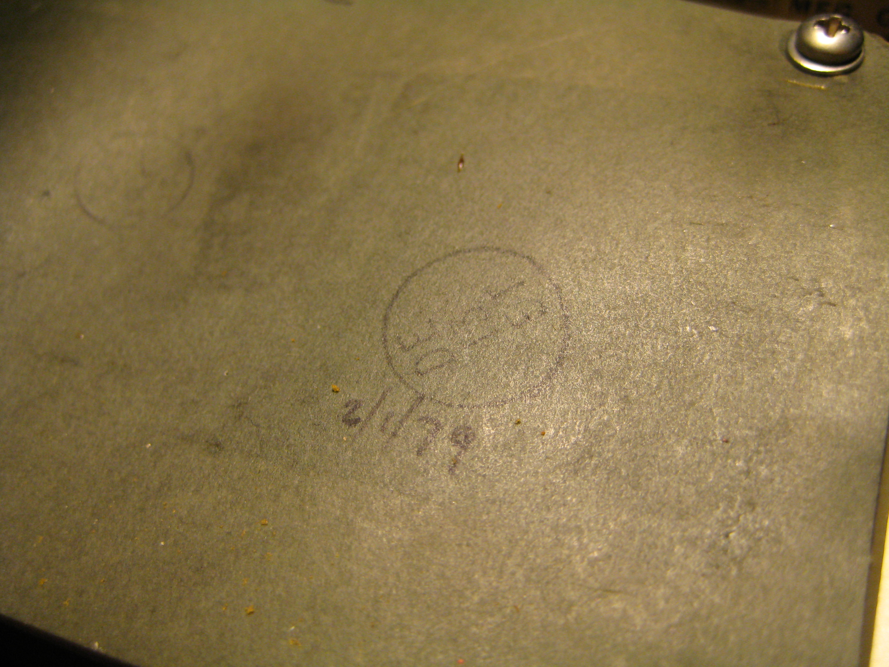
Some of the insulating paper had evidence that people were doing math on it …

Now onto the nasty Ni-CD pack which caused all of the mess. We can see that on the insulating paper, it is dated 1st February 1979 (assuming American format as Dranetz is American).


All of the batteries are tagged Varta 500mAh Ni-CD cells, and they’ve all pretty much leaked. The plastic around the packs have peeled and torn due to the corrosion buildup on the outer casing of the batteries causing pressure on the heatshrink. The gas itself has gone on to corrode connectors, PCBs and other things inside the device. Nasty.
Here’s the transformer card which interfaces to each phase – note the corrosion on the 2nd transformer from the right …

One thing captured my attention – the large stack of multi-ganged switches. Wow. They must have had lots of patience to assemble these …

So, that ends our disassembly and disposal of the unit. But not before showing you guys this – all of the unique chips which have been de-socketed – brands like Philips, Intel, Signetics, RCA, Fujitsu (possibly), TI, Motorola and National Semiconductor.

And yes, for the keen-eyed, there is a 555 timer in this piece of test equipment!
The chip part numbers include:
| 41048DC – ? |
| 84702A – PROM? |
| CA3094E – High Output Current Operational Transconductance Amplifier |
| CA3130E – 15Mhz BiMOS Opamp with MOSFET Input/CMOS Output |
| CD4011UBF – CMOS Quad Unbuffered NAND gate |
| CD4016CJ – CMOS Quad Bilateral Switch |
| CD4503BCJ – CMOS Non Inverting Tri-state Buffer |
| D2316E – ROM memory |
| D4040 – 4-bit microprocessor |
| D4289 – Standard Memory Interface |
| D5101L – 256x4bit Static CMOS RAM |
| D8048 – MCS-48 microcontroller |
| DM7406J – TTL Hex Inverter Buffer |
| LM555CN – Single Timer |
| LM747CF – Dual 741 Opamp |
| MC14001B – Quad 2 Input NOR Gate |
| MC14011B – Quad 2 Input NAND Gate |
| MC14013B – Dual Type-D Flip-Flop |
| MC14023B – Triple 3 Input NAND Gate |
| MC14027B – Dual J-K Flip-Flop |
| MC14042B – Quad Transperant Latch |
| MC14046B – Phase Locked Loop |
| MC14049UB – Hex Inverter |
| MC14050B – Hex Buffer |
| MC14066B – Quad Analog Switch/Multiplexer |
| MC14081B – Quad 2 Input AND Gate |
| MC14538B – Triple Serial Adder |
| MM5313N – Digital Clock |
| MM74C164J – 8-bit Parallel-Out Serial Shift Register |
| MP7520JN – 10-bit multiplying D/A Converter |
| P4201A – Clock Generator |
| SAA1027 – Stepper Motor Drive Circuit |
| SN75469J – High Voltage High Current Darlington Array |
| UA747DC – Dual Frequency Compensated Opamp |
What you describe as “trauma” and “catastrophic failure”, is in my opinion fairly normal damage from decades of time and use, for a device built in the 1970’s. Brown areas of PC boards show decades of heat. Fuses blow, that is normal. All batteries fail and leak and crystallize over decades and should be removed to avoid consequences of leakage. Corrosion of course can vary greatly but is to be expected over four decades. Components fail over decades, that happens, but many do not. The key word here is “decades” – damage that occurs over years, might appear to be from a short-term event, but that’s not so.
My point, and not to be a jerk about it, is that if someone in the 21st century sees this kind of apparent damage in equipment of this vintage, they should NOT assume the item is beyond repair. I’m a 60-year-old digital engineer, I repair stuff like this ALL THE TIME. So do other people (irrespective of age). There’s pages on my Web site, and others, about such repairs.
Thanks for your comment.
Upon further thought, yes, I do agree with your points about such burn marks, and accumulated damage – I’m no stranger to this having seen many paper-PCBs in power supplies brown, sometimes quite significantly, in things like external drive enclosure power supplies and computer power supplies and consider it to be normal. Provided there is no bad smell, cracked transistor casings or “legs left standing in the air”, it can (and often is) still operational.
Considering its probable history as a line analyser, normally deployed where power quality is poor (i.e. suffering from sags, surges, impulses, harmonics, etc), the stress on this device though its lifetime is likely to have been quite high and it wouldn’t surprise me if insulation degradation had taken its toll on all of the primary side and power supply series regulation components. Of course, anything can be repaired if one has access to the parts (or specs/schematics to procure equivalent replacements) and is willing to dedicate enough money, time and effort to restore it, anything is possible. I’m not trying to discourage people in repairing devices – but more to recognize what damaged components look like, rather than just “replacing the fuse and hoping for the best”. After all, with salvaged gear, the condition of the gear is an unknown, and I’m no advocate of plugging it in and just “trying it” – especially if I spot any paper-type capacitors on the primary (ala Apple II’s).
Unfortunately, when things are taken off the street, they don’t come with any guarantees and former owners are often not aware and devices not designed to have their batteries removed. This particular unit is one of them – battery buried inside the frame, bolted and soldered in. I guess it’s the same thing with old 386 motherboards and their CMOS battery, which I’ve repaired a few of. It’s a big shame too, as larger batteries can have enough electrolyte to corrode PCB traces to hell … almost never to return.
Don’t get me wrong – I’m not the sort to cannibalize and just throw anything that doesn’t work into the bin – but there are some repairs within my grasp, and others which … maybe a tad out of reach. This may be time related (I’m always busy with study), technical (lets face it, I’m no electronics veteran (heck, I’m 23 years old for all it counts – almost all of these things are older than I am), but I do enjoy it as a self-educated hobby pursuit) and cost (maybe parts and schematics aren’t available). If it’s really worthwhile in my eyes, I would still keep it in a broken state (in the hope a second, non-functional unit would appear and make repairs a lot easier), but as it is, I have hoarded too much :). The fact that I managed to sneak this guy out of there while the garbage collector had his back to the pile was already a lucky save …
I have visited your site, especially when dealing with the Kaypro 4 that I had been donated (and managed to eventually get working, although the worn master floppy and lack of copies from the donor did some CP/M utilities lost) and have found your website to be quite useful, as well as interesting in that pursuit. That one’s been kept nice and safe now – that’s a keeper.
Thanks for your thoughtful response to my previous post. I have a few of these units now; contact me if you want to sell your boards and/or parts.
Hi Lui, my name is Fellipe, I’m electrical engineering student! At this moment I just started my conclusion course work. I’m will desing a power quality analyser. Now, I’m just studing about the power quality monitoring in the past. I saw this device on Dugan textbook and I have any doubts about it.
In your opinion, what is the drawbacks of this equipment nowdays? Thanks!!!
Sorry for my poor English!!!
Removing the 230v option would eliminate the burned transformer?
I have a 606 which I purchased used many years ago. It was in working condition far as I know ! Battery wasn`t holding it`s charge. I removed the battery pack for further processing and rebuild. I was lucky enough to posses a board puller in the shop which made disassembly duck soup ! There is a battery distributor who will rebuild the battery for me !